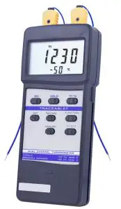
TRACEABLE 4029 Dual-Channel Thermometer
SPECIFICATIONS
| Circuit | ONS Circuit Custom one– chip of microprocessor LSI with thermocouple linearity correction circuit |
| Display | Dual function meter’s display, 13 mm (0.5”), Super large LCD display with annunciator |
| Measurement | Two channel temperature input (T1, T2), differential temperature measurement (T1-T2), °C/°F, 0.1°/1° degree |
| Measurement Range | –50 to 1230°C (–58 to 1999°F) |
| Polarity | Automatic switching, ‘—’ indicates negative polarity |
| Sensor Type | Thermocouple K (NiCr—NiAl) |
| Input Impedance | 10 Mega ohm |
| Sampling Time | Approx. 0.8—1.0 second |
| Memory Recall | Records Maximum, Minimum readings with RECALL |
| Over input indication | Indication of “- – – -” |
| Operating Temperature | 0 to 50°C (32 to 122°F) |
| Operating Humidity | Max. 80% RH |
| Power Supply | 006P DC 9V battery (Heavy duty type) |
| Power Current | Approx. DC 6.2 mA |
| Size | 7⅛ x 2⅞ x 11 /3 inches |
| Weight | 9¾ ounces |
| Accessories | Temperature probe, carrying case (not included) |
FRONT PANEL DESCRIPTION
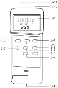
3-1 Display3-2 Power On button3-3 Data Hold button3-4 °C/°F button3-5 Power Off button3-6 Memory “Record” button3-7 Memory “Call” button3-8 Function button (T1, T2, T1-T2)3-9 1°/0.1° button3-10 Battery Compartment/ Cover3-11 T1 Input Socket3-12 T2 Input Socket
MEASURING PROCEDURE
- Push the “power off button” (3-2, Fig. 1) to let the instrument power “ON”.
- Determine temperature unit to °C or °F by pushing the ” °C/°F Button ” (3-4, Fig. 1) Then the display will show the temperature unit of °C or °F.
- Determine the display resolution to 0.1° or 1° by pushing the “1°/0.1° Button”.
- One probe measurement: Insert one temperature probe plug into the socket T1 (3-11), then push the “Function Button” (3-8, Fig. 1) until the display show the marker “T1” display will show the temperature reading that measured from the probe.
- Two probe (dual channel) & differential measurement:a. Insert second temperature probe plug into the “T1 Socket” (3-11, Fig. 1).b. Insert second temperature probe plug into the “T2 Socket” (3-12, Fig. 1).c. The main display (upper display) will show the temperature reading of the first probe (T1) & the lower display will show the temperature reading of second probe (T2), push the “Function Button” (3-8, Fig. 1) until “T1” appears on the display.d. The main display (upper display) will show the temperature reading of second probe (T2) & the lower display will show the temperature reading of the first probe (T1), push the “Function Button” (3-8, Fig. 1) until “T2” appears on the display.e. The main display (upper display) will show the differential temperature reading of the first and second probe (T1-T2) and the lower display will show the temperature reading of the first probe (T1), push the “Function Button” (3-8, Fig. 1) until “T1-T2” appears on the display.
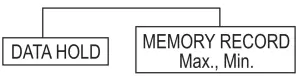
DATA HOLD
- During the measurement. Push the “Data Hold Button” (3-3, Fig. 1) will hold the display values & LCD will show the “D.H” marker.
- Push the “Data Hold Button” again will release the data hold function.
DATA RECORD
- The DATA RECORD function displays the maximum, and minimum readings. To start the DATA RECORD function, press the “Record Button” (3-6, Fig. 1) once. “REC” will appear on the LCD display.
- With the “REC” appearing on the display.a. Push the “CALL Button” (3-7, Fig. 1) once, then the “Max” marker along with the maximum values will appear on the LCD display.b. Push the “CALL Button” once, then the “Min” marker along with the minimum values will appear on the LCD display.c. When running the “Record” function, pushing the “Record Button” once again will stop the “Record” function.d. After stopping the “Record” function, the marker of “REC”, “Max”, “Min” will disappear.
MAIN PROCEDURES
OPTIONAL MEASURING PROCEDURES
MEASURING CONSIDERATION
Insert the probe plug into the temperature input socket T1 (3-11) of T2 (3-12), taking care to observe the correct polarity. Greatest accuracy is achieved when the probe plug is first inserted into the thermometer socket (T1,T2), or if the probe is changed, the plug must be allowed to stabilize at temperature of the socket, which is in thermal contact with cold junction compensation device. This will take a couple of minutes and only applies if the probe plug has previously been exposed to an ambient temperature different to that thermometer.
BATTERY REPLACEMENT
When the left corner of LCD display show “LBT”, it indicates a normal battery output of less than 6.5V 7.5V. It is necessary to replace the battery. However, in– spec measurement may still be made for several hours after low battery indicator appears before the instrument becomes inaccurate. Slide the Battery Cover (3-10, Fig. 1) away from the instrument and remove the battery. Replace with 9V battery (heavy duty type) and replace the cover. Make sure the battery cover is secured after changing the battery.
WARRANTY, SERVICE, OR RECALIBRATION
For warranty, service, or recalibration, contact:
TRACEABLE® PRODUCTS12554 Old Galveston Rd. Suite B230Webster, Texas 77598 USAPh. 281 482-1714 · Fax 281 482-9448E-mail suppor[email protected]www.traceable.com
Traceable® Products are ISO 9001:2018 Quality Certified by DNV and ISO/IEC 17025:2017 accredited as a Calibration Laboratory by A2LA.
 report this ad
Traceable® is a registered trademark of Cole-Parmer.©2020 Traceable® Products. 92-4029-20 Rev. 4 042320
References
[xyz-ips snippet=”download-snippet”]