![]()
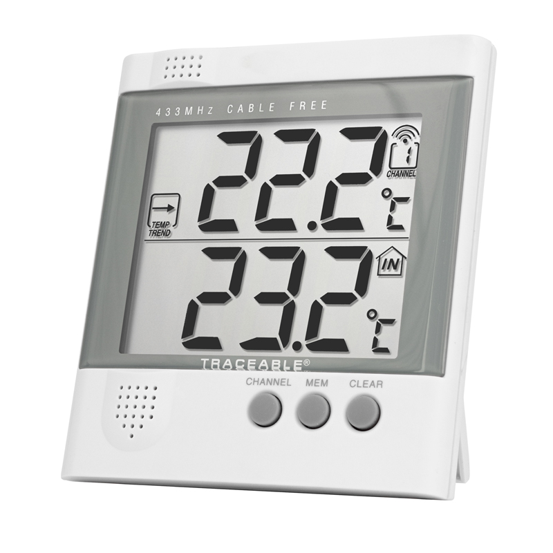
TRACEABLE Radio-signal Remote Thermometer Instructions

SPECIFICATIONS
- Display—Main unit: two-line 1″ LCDRemote unit: 3/8″ LCD
- Temperature—Main unit IN range: –9.9 to 158.0°F (–9.9 to 70.0°C)Main unit OUT range: –58.0 to 158.0°F (–50.0 to 70.0°C)Main unit resolution: 0.1°Main unit accuracy: ±1.0°CMain unit ambient operating range: 23.0 to 122.0°F (–5.0 to 50.0°C)Remote unit OUT (probe): –50.0 to 70.0°C onlyRemote unit resolution: 0.1°Remote unit accuracy: ±1.0°CRemote unit ambient operating range: –20.0 to 60.0°C only
- RF transmission frequency: 433 MHzNo. of remote units: maximum 3RF transmission range: maximum 100′ (30 m)Temperature sensing cycle: approximately 30 sec
- Power—Main unit: two AA 1.5-volt alkaline batteriesRemote unit: two AAA 1.5-volt alkaline batteries
- Case: ABS plastic
- Size/Weight—Main unit: 4.6 x 4.2 x 1″ (117 x 107 x 26 mm), 8.8 oz (250 g)Remote unit: 3.6 x 2.4 x 0.8″ (92 x 60 x 21 mm), 3.5 oz (100 g)
FEATURES
- The unit is an easy-to-use, state-of-the-art thermometer. The basic package comes with a main unit, which is the temperature receiver, and a remote unit with an internal sensor and external sensor.
- The main unit has extra-large readouts for indoor temperatures and temperatures transmitted by the remote unit. The main unit can support up to three remote units.
- The main unit is capable of monitoring temperature changes of remote sites. Set upper and lower temperature limits and the alarm will go off when limits are exceeded. The maximum and minimum temperature of different sites can also be retrieved quickly.
- No wire installation is required between the main and remote units. The units operate at 433 MHz and can be used in the U.S. and most places in Continental Europe.
Compliance
This product complies with standards and specifications of BZT, FCC and article number 334 of PTT.
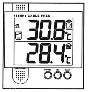
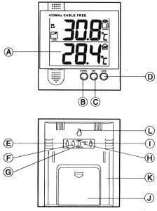
Figure 1: Main unit configuration
Main Unit (see fig. 1)
- A. EXTRA-LARGE LCD Facilitates easy reading of remote and indoor temperatures.
- B. CHANNEL button Selects among different channels.
- C. MEM button Recalls the maximum or minimum temperature of individual channels.
- D. CLEAR button Clears the maximum and minimum temperatures of individual channels.
- E. HI/LO button Sets the upper or lower temperature alarm limits of individual channels.
- F. ▲ button Sets the value for the upper or lower temperature of individual channels.
- G. ON/OFF TEMP AL button Turns on or off the temperature alarm of individual channels.
- H. RESET button Returns all settings to default values and erases temperature memories.
- I. °C/°F switch Selects between degrees Celsius (°C) and degrees Fahrenheit (°F).
- J. Battery compartment Accommodates two AA 1.5-volt batteries.
- K. Retractable stand For standing the main unit on a flat surface.
Remote Unit (see fig. 2)
- A. LCD Displays the current temperature monitored by the remote unit.
- B. LED indicator Flashes when the remote unit transmits a reading.
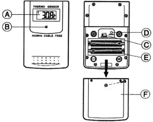
Figure 2: Remote unit configuration
- C. CHANNEL switch Designates the remote unit Channel 1, Channel 2 or Channel 3.
- D. RESET button Returns all settings to default values.
- E. Battery compartment Accommodates two AAA batteries.
- F. Battery door
BEFORE BEGINNING
- Assign different channels to different remote units.
- Insert batteries for remote units before doing so for the main unit.
- Place the main unit as close as possible to the remote unit, reset the main unit after installing batteries. This will ensure easier synchronization between the transmission and reception of signals.
- Position the remote unit and main unit within effective transmission range, which, in usual circumstances is 50 to 100 feet (15 to 30 meters).
Note: The effective range is significantly affected by building materials and where the main and remote units are positioned. Try various setups for best results.
Important: Though the remote units are weatherproof, they should be placed away from direct sunlight, rain, or snow.
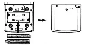
BATTERY AND CHANNEL INSTALLATION: REMOTE UNIT
The remote unit uses two AAA batteries. To install them:
- Remove the screws on the battery compartment.
- Select the channel number on the CHANNEL slide switch.
- Insert the batteries according to the polarities shown.

- Replace the battery compartment door and secure its screws.
Replace the batteries when the low-battery indicator of the particular channel lights up on the main unit. (Repeat the steps described in section, “Before Beginning”.)
Note: Once a channel is assigned to a remote unit, it can only be changed by removing the batteries or resetting the unit.
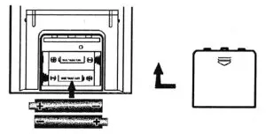
BATTERY INSTALLATION: MAIN UNIT
The main unit uses two AA batteries. To install them:
- Slide open the battery compartment door.
- Insert the batteries strictly according to the polarities shown.
- Replace the battery compartment door.
Replace the batteries when the low-battery indicator of the indoor temperature lights up. (Repeat the steps described in section, “Before Beginning”.)
TWO SENSORS
Each remote module has two sensors. The internal (ambient) sensor is located inside the case toward the bottom of the remote module. It is ideal for monitoring air temperatures. It is automatically in use and in the circuit when the external sensor is not plugged in.
The second sensor is the external one. Use it to monitor liquids, gases, and semisolids. The external sensor is automatically in use when it is plugged into the remote module. Plugging in the external sensor removes the internal sensor from the circuit. The waterproof external sensor and 10-foot cable perform accurately even when both are under water.
GETTING STARTED
Once batteries are in place for the remote units, they will start transmitting temperature readings at 30-second intervals.
The main unit will also start searching for signals for about 2 minutes once batteries are installed. Upon successful reception, the individual channel temperatures will be displayed on the top line and the indoor temperature on the bottom line. The main unit will automatically update its readings at about 30-second intervals.
If no signals are received, blanks “- – -” will be displayed and the kinetic wave icon will show “ ![]() ”. Press CHANNEL and MEM simultaneously to force another search for 30 seconds. This is useful in synchronizing the transmission and reception of the remote and main unit.
”. Press CHANNEL and MEM simultaneously to force another search for 30 seconds. This is useful in synchronizing the transmission and reception of the remote and main unit.
Repeat this step whenever you find discrepancies between the reading shown on the main unit and that on the respective remote unit.
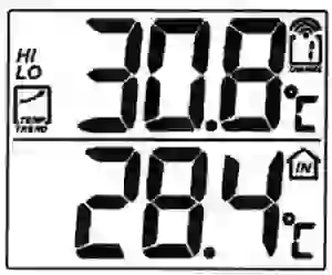
HOW TO CHECK REMOTE AND INDOOR TEMPERATURES
The indoor temperature is shown on the lower line of the display.The remote readings are on the upper display. For the remote sites or channels, press CHANNEL to go from one channel to another. The kinetic wave display on the channel number indicates the reception of that particular channel is in good order.
If no readings are received from one particular channel for more than 2 minutes, blanks, “- – -” will be displayed until further readings are successfully searched. Verify the remote unit is sound and secure. Wait for a little while or press CHANNEL and MEM simultaneously to force an immediate search. No reading will be shown if no remote unit is assigned to that channel.
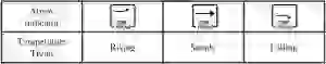
The temperature trend indicator on the screen shows the trend of readings collected at that particular remote site. Three trends, rising, steady, and falling, will be shown.
If the temperature goes above or below the temperature measuring range of the main unit or the remote unit (stated in “Specifications” section), the display will show “HHH” or “LLL”.
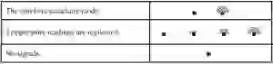
HOW TO READ THE KINETIC WAVE DISPLAY
The kinetic wave display shows the signal receiving status of the main unit. There are three possible forms.
MAXIMUM AND MINIMUM TEMPERATURES
The maximum and minimum recorded indoor temperatures and those ofeach channel will automatically be stored in memory. To display them:
- Select the channel to be checked.
- Press MEM once to display the maximum temperature. Press again to display the minimum temperature. The respective indicators (MAX or MIN) will be displayed. Press again to read current temperature.
To clear the memory, press CLEAR. All segments of the display will light up for 2 seconds. The display will return to the last screen with maximum and minimum temperatures erased from memory.
The maximum and minimum temperatures will now be the same value as the current one until different readings are recorded.
HOW TO USE TEMPERATURE ALARMS
The temperature alarms allow setting upper and lower limits of readings for individual channels. The alarm will sound if a limit is exceeded. To set the alarm:
- Select the channel to be set.
- Press the HI/LO button for the upper (HI) or lower (LO) limit. An “OFF” message will be displayed if the alarm for that limit is turned off.
- Use the ADVANCE (▲) button to set the upper or lower temperature.If this is the first time setting limits, the lower limit will start from -58 °F (-50°C) and the upper limit 158°F (+70°C). Otherwise, the reading will start from the temperature last selected.Each press of the button will increase the temperature by 1 degree. Holding the button down will step in increments of 5 degrees.
- Press TEMP AL ON/OFF button to switch off the “OFF” message. The set limit will be displayed.
- Press HI/LO button to set another limit or return to normal display. The respective HI, LO, or both indicators will light up to signify the status of the alarm.
When an alarm goes off, the display will switch to the respective channel with the display flashing. If undisturbed, the alarm will sound for a minute. Press any key to mute the alarm momentarily. The alarm will sound again if the temperature still exceeds the set limit.
To disable the alarm, select the channel and use ON/OFF TEMP AL button to turn it off.
If upper and lower temperatures for more than one channel have been set, and the limits are exceeded for more than one channel, the alarm will sound with the display switching from one channel to another at 5-second intervals.
DISCONNECTED SIGNALS
If without obvious reasons the display for a particular channel goes blank, press CHANNEL and MEM to force an immediate search.If that fails, check:
- The remote unit for that channel to see if it is still in place.
- The batteries of both the remote unit and the main unit. Replace as necessary.
TRANSMISSION COLLISIONSignals from other radio devices may interfere with those of this product and cause temporary reception failure. This is normal and does not affect the general performance of the product. The transmission and reception of temperature readings will resume once the interference recedes.
NOTE ON °C AND °FThe unit of temperature display is selected on the °C/°F slide switch on main unit. Select °C for Celsius or °F for Fahrenheit.
Note that the remote unit only displays temperature in °C.
LOW BATTERY WARNINGWhen it is time to replace batteries, the respective low-battery indicator will show up when the respective channel is selected. The battery indicator for the main unit will be shown on the indoor temperature display.
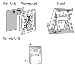
HOW TO USE THE BENCH STAND OR WALL MOUNTINGThe main unit has a retractable bench stand, which when flipped open, can support the unit on a flat surface. Or, close the stand and mount the unit on a wall using the recessed screw hole.
THE RESET BUTTONThis button is only used then the unit is operating in an unfavorable way or malfunctioning. Use a blunt stylus or straightened paper clip to hold down the button. All settings will return to default values.
PRECAUTIONS
This product is engineered to provide years of satisfactory service ifhandled carefully. Here are a few precautions:
- Do not immerse the unit in water.
- Do not clean the unit with abrasive or corrosive materials. They may scratch the plastic parts and corrode the electronic circuit.
- Do not subject the unit to excessive force, shock , dust, temperature or humidity, which may result in malfunction, shorter electronic life span, damaged battery, and distorted parts.
- Do not tamper with the unit’s internal components. Doing so will invalidate the warranty on the unit and may cause unnecessary damage.The unit contains no user-serviceable parts.
- Only use fresh batteries as specified. Do not mix new and old batteries.
- Read the user’s manual thoroughly before operating the unit.
OPERATIONAL DIFFICULTIES
If this temperature meter does not function properly for any reason, please replace the batteries with new, high-quality batteries (see “Battery Installation” sections). Low battery power can occasionally cause any number of “apparent” operational difficulties. Replacing the batteries with new fresh batteries will solve most difficulties.
What to do if the unit appears to not be receiving a signal.—Suggestions
Keep in mind that the remote transmitter sends a signal to the main receiver every thirty seconds. Be patient, wait 2 minutes to see if a signal has been received.
Make certain that the channel number on the remote transmitter (displayed on the remote transmitter LCD) and the channel number on the main receiver (displayed on the receiver LCD) are identical.
If there are two or more remote transmitters, make certain that none is set to the same channel number.
Remove the battery cover on the main receiver (unit with large LCD display). Remove the batteries. Do not put the batteries in until the remote transmitter is activated. The goal is to activate the remote transmitter before the main receiver.
Remove the back panel of the remote transmitter. Remove the batteries, wait 20 seconds, and put them back in the unit. Then, using a stylus or straightened paper clip, press the RESET button. Observe on the remote transmitter LCD a momentary reset to “888” on the display, release the RESET button.
Place the batteries in the main receiver unit. Replace the battery cover. Using a stylus or straightened paper clip, press the RESET button on the main receiver. Observe on the receiver LCD a momentary reset to “888” on the display, release the RESET button.
First make certain that the unit will pick up a nearby signal. Do this by placing the remote transmitter in a vertical position. Place the main receiver (large digital display) in a vertical position approximately 6 feet away from the remote transmitter. There should be no obstructions between the units. Make certain the main receiver is set to the correct channel. On the main receiver simultaneously press the CHANNEL button and the MEM button. This will force the main receiver to search for the signal. Again, make certain the main receiver is still set on the correct channel.
If the main receiver is now displaying the temperature from the remote transmitter then the units are functioning correctly. These units will perform within their limitations. All radio signals are inherently affected by interference or blockage. Like all radio transmitters and receivers, performance is best when there is little or no interference or blockage. Even the most powerful megawatt radio station transmitter is occasionally blocked when driving. Powerful cellular phones (which are simply radio transmitters/ receivers) still “drop” calls when interference or blockage occurs. On occasion it is difficult or impossible to receive a cellular phone dial tone in certain areas of a building.
Some of the causes of interference and blockage are metal, reflective surfaces, motors, elevators, florescent lights with electrically noisy ballasts, sparking environments such as welding, emergency vehicle radios, power lines, portable/mobile radio transmitters and walkie-talkies.
On occasion, momentary interference with the remote transmitter may cause an erroneous minimum or maximum reading to be captured by the main unit.
If two or more remote units in the same area are set to the same channel then any or all main units will probably receive scrambled signals and report erroneous readings.
If the units do not perform when placed further apart, then try the following.
- Place the remote transmitter unit as high as possible.
- Place the remote transmitter in a vertical or stand-up position.
- Place the main receiver in a vertical or stand-up position.
- Place the remote transmitter and the main receiver in locations where the radio signal does not need to be sent through metal panels, thick walls, multilevels, etc.
- Try several locations. Sometimes moving either unit several feet or as little as 6 inches will make a significant difference.
- Try several different orientations. That is, turn the remote transmitter and/or the main receiver unit to the left, then to the right.
- Try setting both the remote transmitter and the main receiver to channel 2.
- Replace the batteries in both units with new alkaline batteries and repeat the above procedures.
On occasion radio-transmitted signals may not work in some environments.If this unit does not work in your environment, call 281 482-1714 for help in answering questions.
ACCESSORIES
Cat. No. 4116 Additional Traceable® Remote Sensor Module with internal and external probe. (May be set to Channel 1, 2, or 3. Total of three modules may be used with the main receiver.
Cat. No. 4117 Accessory Traceable® Stainless-Steel Probe (Triple-purpose probe for liquids, air/gas, and semisolids. Diameter is 1/8-inch. Overall length is 8 1/2 inches. Cable length is 5 feet.)
Cat. No. 4118 Accessory Traceable® External Bottle Probe Probe is sealed in a mini-bottle filled with a glycol solution for “temperature buffering”. Monitors products subjected to door openings in freezers, refrigerators, and incubators. Supplied with magnet and Velcro™ mounting strips plus a 10-foot ultrathin cable. Cable permits refrigerator/freezer doors to be closed on it while still maintaining the door’s seal.
WARRANTY, SERVICE, OR RECALIBRATION
For warranty, service, or recalibration contact:
TRACEABLE® PRODUCTS12554 Old Galveston Rd. Suite B230Webster, Texas 77598 USAPh. 281 482-1714 • Fax 281 482-9448E-mail [email protected] • www.traceable.com
Traceable® Products is ISO 9001:2018 Quality-Certified by DNV and ISO/IEC17025:2017 accredited as a Calibration Laboratory by A2LA.
Traceable® is a registered trademark of Cole-Parmer.© 2020 Traceable® Products. 92-4115-00 Rev. 5 050520
 report this ad
References
[xyz-ips snippet=”download-snippet”]