![]()
TRACEABLE S04566 Memory Card Thermometer Instructions
WARRANTY, SERVICE, OR RECALIBRATIONFor warranty, service, or recalibration, contact:
TRACEABLE® PRODUCTS12554 Old Galveston Rd. Suite B230Webster, Texas 77598 USAPh. 281 482-1714 • Fax 281 482-9448E-mail [email protected] • www.traceable.comTraceable® Products is ISO 9001:2018 Quality-Certified by DNV and ISO/IEC 17025:2017accredited as a Calibration Laboratory by A2LA.
Word® and Excel® are registered trademarks of Microsoft Corporation in the United States and/or other countries. Traceable® is a registered trademark of Cole-Parmer. ©2020 Traceable® Products. 92-6404-10 Rev. 5 060520
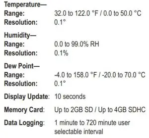
SPECIFICATIONS
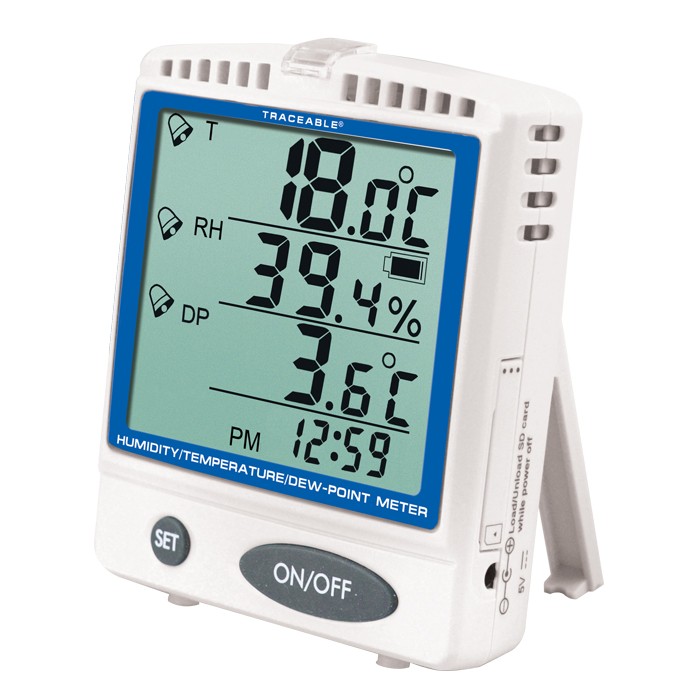
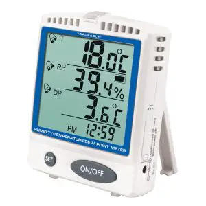
OVERVIEW
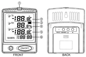
- LED visual alarm indicator
- Ambient Temperature (TA)
- Battery status indicator
- Ambient Relative Humidity
- Dew Point Temperature
- Time-of-day clock (data logger messages will also alternate here)
AC POWER SUPPLY/BATTERY POWER
The meter may be powered the following ways:
Batteries onlyTypical operating time when using the three (3) each AA alkaline batteries only:
- Up to 1 year in display mode only, no data logging, no alarms.
- Up to 1 month with data logging on at a 1 minute recording rate, with no alarms. Higher capacity memory cards require more power to operate; therefore, larger cards will exhaust the batteries more rapidly.

AC power supply onlyIf the AC power supply is being used without batteries, in the event of a power outage, the meter will turn off and data logging will stop.
AC power supply and batteries togetherUsing the AC power supply and batteries together allows the batteries to act as a backup power supply in the event of a power outage.
When using the AC power supply and batteries together, the batteries will need to be replaced periodically to insure they have sufficient power to operate the meter during a power outage (see the “Battery Replacement” section).
DISPLAY MESSAGES
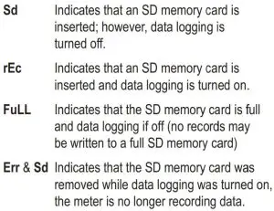
The following messages may appear alternating in place of the time-of-day clock:
SETTING TIME-OF-DAY/DATE
- Turn the meter on by pressing the ON/OFF button.
- Press and hold the SET and ▼ buttons simultaneously for 3 seconds to enter the time-of-day/date setting mode (12H or 24H will flash on the display).
- Press the ▼ or ▲ button to select 12 or 24 hour time format.
- Press the SET button, the year will flash.
- Press the ▼ or ▲ button to increment the Open the file(s) in the desired program (Word®,Excel®, NotePad, WordPad, etc).
To open from Excel®, example:File →Open →All Files (*.*)®locate and select the file →Open →Fixed Width→ Next →place column breaks at 10, 20, 27, 34, and 44 → Finish
PLACEMENT/MOUNTING OPTIONS
Bench Stand – The meter is supplied with a bench stand that is a part of the back of the meter. To use the bench stand, locate the small opening at the corners on the back of the meter. Place your fingernail into the opening and flip the stand out. To close the stand, simply snap it shut.
Wall Mount – Set a screw into the wall at the location desired. The head of the screw will need to slip into the receptacle on the back of the meter, do not set the screw flush to the wall. Once the screw has been set properly, hang the meter in place by sliding the receptacle on the back of the meter over the head of the screw.
Magnet – A magnet is supplied with the meter. Peel the protective paper off the adhesive tape on the magnet. Press the magnet onto the back of the thermometer and mount on any metal surface.
Hook & Loop – Self adhesive hook and loop mounting tape is supplied with the meter. Peel off the protective backing. Adhere one piece to the meter and the other to any clean, flat surface.
ALL OPERATION DIFFICULTIES
If this meter does not function properly for any reason, replace the batteries with new, high-quality alkaline batteries (see the “Battery Replacement” section). Low battery power can occasionally cause an number of “apparent” operational difficulties. Replacing the batteries with new fresh batteries will solve most difficulties.
ERROR CODES
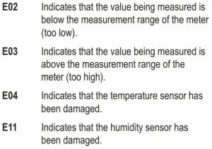
E32/E33 Indicates that the meter has been damaged.
BATTERY REPLACEMENTAn erratic display, faint display, no display, or ![]() appearing on the display are all indicators that the batteries need replacement.
appearing on the display are all indicators that the batteries need replacement.
If the AC power supply is not being used when the batteries are being replaced, the meter will turn off once the batteries have been removed. The meter and data logging will need to be turned back on once the batteries have been replaced.
If the AC power supply is being used when the batteries are being replaced, the meter will continue to function without interruption.
Remove the battery cover located on the back of the meter. Remove the exhausted batteries and replace them with three (3) new AA alkaline batteries. Make certain to insert the new batteries with the proper polarity as indicated by the illustration in the battery compartment. Replace the battery cover.
TURNING ON/OFF DATA LOGGING
Prior to starting data logging:
- Make certain that the time-of-day and date have been set properly (see the “Setting Time-of-Day/ Date” section). The recorded data will be time/ date stamped using the time-of-day/date setting.
- Make certain that an SD/SDHC memory card is inserted into the meter (see the “Inserting/ Removing SD Memory Card” section).
- Set the desired °F/°C display mode (see the “Displaying °F or °C” section).
- Set the desired data logger recording rate (see the “Adjusting Data Logger Recording Rate” section).
To toggle data logging On/Off, press and hold the SET button for 6 seconds (each time this is performed, it will toggle from on/off and from off/on):
OFf rEc indicates that the data logging function is off.
ON rEc indicates that the data logging function is on.
While data logging is occurring, the clock section will alternate between displaying the time and rEc.
If the meter is turned off, the data logging will also be turned off. When the meter is turned on, data logging must be turned back on by using the above procedure.
If the SD card is removed while data logging is turned on, Err and Sd will alternate on the display in place of the clock to indicate that the meter is no longer recording data. Insert the SD card to return to data logging.
The following will cause data logging to stop/turn off:
- Turning the meter off
- Low battery power (
 ), when using batteries only
 - Power failure, when using the AC power supply only
- Removing the SD memory card
- Changing the time-of-day/date
- Changing the data logger recording rate
- Changing the High/Low alarm settings
- Changing display from °F/°C, °C/°F
- Pressing the RESET button
Once data logging has been stopped, it must be turned back on.
DATA LOGGING FILE FORMAT/STRUCTURE
With data logging turned on (see the “Turning On/Off
Data Logging” section), the meter will write a file to the SD memory card. The file created is a standard text (.TXT) file.
Once data logging has started, the filename created is based on the start date (month and day number) and time.
Example: Start 11/28/2013 at 16:48, will create a file with the name “11281648.TXT”.
The maximum size per file is 30,000 records. During continuous data logging, once the maximum file size has been reached, a new file is automatically created utilizing the same file naming method. A file containing 30,000 records represents over 20 days of minute by minute data. Depending on the selected data logger recording rate and the duration, continuous data logging may generate numerous files containing data.
The file created is a fixed width data file that may be read utilizing any computer application capable of reading “.TXT” files (Word®, Excel®, NotePad, WordPad, etc).
The text file is structured as follows: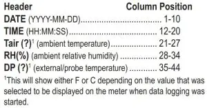
READING THE DATA FILE(S) FROM THE SD CARD
- Remove the SD memory card from the meter (see the “Inserting/Removing SD Memory Card” section).
- Insert the SD memory card into the supplied USB SD card reader. (If the computer being used has a built-in SD card reader, the USB card reader is not required.)
- Plug the USB SD card reader into an available USB port on the computer. The first time the USB card reader is plugged in to the computer, drivers will automatically be installed to allow the card reader to function.
- Browse to the SD card and select the file(s) to view. display to the correct value. This is the last 2 digits of the year.Example: 2013 is displayed as 13.
- Press the SET button, the month will flash.
- Press the ▼ or ▲ button to increment the display to the correct value.
- Press the SET button, the day number will flash.
- Press the ▼ or ▲ button to increment the display to the correct value.
- Press the SET button, the time-of-day hours will flash.
- Press the ▼ or ▲ button to increment the display to the correct value.
- Press the SET button, the time-of-day minutes will flash.
- Press the ▼ or ▲ button to increment the display to the correct value.
- Press the SET button, the display will return to the current temperature/relative humidity display.
DISPLAYING °F OR °C
With the meter turned on, to toggle the display between reading Fahrenheit or Celsius, press and hold the p button for 3 seconds.
When using the data logging function, the temperature values recorded will match the selected display unit (°F or °C).
MINIMUM AND MAXIMUM MEMORY
There are six points that are automatically recorded into memory:
- Minimum Ambient Temperature Achieved
- Maximum Ambient Temperature Achieved
- Minimum Ambient Relative Humidity Achieved
- Maximum Ambient Relative Humidity Achieved
- Minimum Dew Point Temperature Achieved
- Maximum Dew Point Temperature Achieved
Minimum and maximum memories are NOT programmable.
The minimum value recorded into memory is the minimum reading achieved since the last time the memory was cleared. The maximum value recorded into memory is the maximum reading achieved since the last time the memory was cleared. The minimum and maximum memories are maintained over the period since the memory was last cleared.
VIEWING MINIMUM/MAXIMUM MEMORYPress the MIN/MAX button, the display will show “MIN” at the bottom left side of the display indicating that the minimum memory values are being displayed.
Press the MIN/MAX button a second time, the display will show “MAX” at the bottom left side of the display indicating that the maximum memory values are being displayed.
Press the MIN/MAX button a third time to return to the current temperature/humidity display (MIN/MAX will no longer appear on the display).
CLEARING THE MINIMUM/MAXIMUM MEMORIES
Clearing the Minimum/Maximum memories will set both the minimum and maximum values for all readings to the current display readings.
The meter does not have to be in the Min/Max memory display mode to clear the minimum/ maximum memories.
To clear the minimum and maximum memories, press and hold the MIN/MAX button for 3 seconds, all of the LCD segments will appear on the display for approximately 3 seconds indicating that the minimum and maximum memories have been cleared.
The minimum and maximum memories are also cleared when the meter is turned off.
ALARMSIndependent High/Low alarms may be set for all readings (ambient temperature, relative humidity and dew point temperature). Temperature alarm limits may be set in 0.1° increments. Relative humidity alarm limits may be set in 0.1% RH increments.
Each High/Low alarm limit may be independently enabled/disabled allowing selecting of high alarm only, low alarm only, or both high and low alarm monitoring.
SETTING HIGH/LOW ALARM LIMITS
While setting the High/Low alarm limits, if no alarm limit is desired for the value being displayed, press the MIN/MAX button, “–.-” will appear on the display indicating the alarm for the value is disabled.
Once a high and/or low alarm value has been set for a reading, the alarm will be enabled. % appearing to the left of the display value indicates that an alarm is enabled for that reading. Each readings High/Low alarm limit may be independently enabled/disabled allowing the selection of high alarm only, low alarm only, or both high and low alarm monitoring. % appearing will indicate that either a high alarm, low alarm or both high and low alarms are enabled for that reading.
- Press and hold the SET button for 3 seconds, release the SET button when “SET” appears at the bottom right side of the display in place of the time-of-day.
- The low alarm limit for the ambient temperature will appear. The alarm value and “Lo” will flash on the display.
- Press the ▼ or ▲ button to increment the display to the desired low alarm value.
- Press the SET button. The high alarm limit for the ambient temperature will appear. The alarm value and “Hi” will flash on the display.
- Press the ▼ or ▲ button to increment the display to the desired high alarm value.
- Press the SET button. The low alarm limit for the ambient relative humidity will appear. The alarm value and “Lo” will flash on the display.
- Press the ▼ or ▲ button to increment the display to the desired low alarm value.
- Press the SET button. The high alarm limit for the ambient relative humidity will appear. The alarm value and “Hi” will flash on the display.
- Press the ▼ or ▲ button to increment the display to the desired high alarm value.
- Press the SET button. The low alarm limit for the dew point temperature will appear. The alarm value and “Lo” will flash on the display.
- Press the ▼ or ▲ button to increment the display to the desired low alarm value.
- Press the SET button. The high alarm limit for the dew point temperature will appear. The alarm value and “Hi” will be flashing on the display.
- Press the ▼ or ▲ button to increment the display to the desired high alarm value.
- Press the SET button. The data logging rate will flash on the display (see the “Adjusting Data Logger Recording Rate” section).
- Press the SET button to return to the current temperature/humidity display.
VIEWING HIGH/LOW ALARM LIMITSOnce alarm limits have been set, follow the steps in the “Setting High/Low Alarm Limits” section to view the values that have been set. If no changes are desired, do not press the ▲ or ▼ buttons, simply press the SET button to move to the next value.
DISABLE/ENABLE HIGH/LOW ALARM LIMITSOnce alarm limits have been set, follow the steps in the “Setting High/Low Alarm Limits” section to view the values that have been set. Press the SET button to cycle through the values that have been set.
An alarm limit may be disabled while being displayed by pressing the MIN/MAX button, “- -.-” will appear on the display indicating the alarm for the value is disabled. When an alarm value is disabled, the alarm value previously set will be cleared.
To enable an alarm that has been disabled, while viewing the disabled alarm (“- -.-”), press the ▼ or ▲ button to increment the value to the desired alarm value. With an alarm value selected (“- -.-” no longer appearing), the alarm will be enabled.
Each High/Low alarm limit may be independently enabled/disabled allowing selecting of high alarm only, low alarm only, or both high and low alarm monitoring.
ALARM SOUNDINGWith an alarm enabled, when a reading being measured is outside the alarm limit that has been set (equal to or lower than the low alarm set point, or equal to or greater than the high alarm set point):
- will flash on the display next to the measurement that is alarming (ambient temperature, ambient relative humidity or probe temperature). will continue to flash next to the measurement.
- The red LED will flash continuously for the first 10 seconds, and will then flash every 10 seconds until the measured value returns to an in-range condition or user acknowledges the alarm.
- The audible alarm will sound continuously for the first 10 seconds, and will then sound every 10 seconds until user acknowledges the alarm by pressing ON/OFF.
While alarming, the sound may be turned off by pressing the SET button (“Off” will appear on the display), it is not recommended to turn off the alarm sound. This will turn off the alarm sound and no audible alarms will sound while the alarm sound is turned off. The alarm sound may only be turned back on by reaching and alarm condition and pressing the SET button to turn the sound back on; therefore, it is not recommended to turn off the alarm sound. The flashing ![]() and red LED alarm are not affected by this setting.
and red LED alarm are not affected by this setting.
DATA LOGGERThe built-in data logger is capable of utilizing SD (2GB maximum) and SDHC (4GB maximum) memory cards.
The sampling rate for the data logger may be set to record readings from every 1 minute to every 720 minutes in 1 minute increments. A 1 minute interval will record 1440 readings/day. A 720 minute interval will record 2 readings/day.
SD CARD SELECTIONThe supplied 256MB SD memory card is ready for immediate use. When utilizing 3rd party SD/ SDHC cards, insure that they are formatted as FAT16 or FAT32, NTFS format is not supported. SD cards up to 2GB and SDHC cards up to 4GB are supported. Cards over 4GB and MMC/SDXC cards are not supported.
The supplied 256MB SD card is capable of storing 5.9 million readings (over 10 years of readings at 1 minute intervals).
Higher capacity memory cards require more power to operate; therefore, larger cards will exhaust the batteries more rapidly (see the “AC Power Supply/Battery Power” section).
INSERTING/REMOVING SD MEMORY CARD
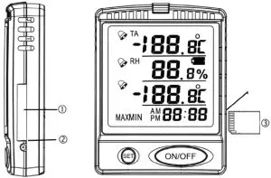
- SD card door
- Lift up here to open SD card door
- Proper SD memory card orientation for inserting
To remove the SD memory card:
- Turn off data logging (see the “Turning On/Off Data Logging” section).
- Turn the meter off, by pressing the ON/OFF button.
- Open the SD card door by lifting up on the bottom of the door.
- Push the SD memory card until it “clicks”, then release to allow the card to be ejected.
To insert the SD memory card:
- Turn the meter off, by pressing the ON/OFF button.
- Open the SD card door by lifting up on the bottom of the door.
- Make certain that the SD memory card is oriented properly (see image) and insert by pushing the card until it “clicks”.
- Close the SD card door by snapping it shut.
- Turn the meter on by pressing the ON/OFF button.
- Turn data logging on, if desired (see the “Turning On/Off Data Logging” section).
ADJUSTING DATA LOGGER RECORDING RATE
The sampling rate for the data logger may be set to record readings from every 1 minute to every 720 minutes in 1 minute increments. A 1 minute interval will record 1440 readings/day. A 720 minute interval will record 2 readings/day.
- Press and hold the SET button for 3 seconds, release the SET button when “SET” appears at the bottom right side of the display in place of the clock.
- The low alarm limit for the ambient temperature will appear.
- Press the SET button six (6) times to pass through the alarm set-points, rAtE should appear on the display.
- The number flashing is the data logger recording interval (expressed in minutes). Press the ▼ or ▲ button to increment the display to the desired value.
- With the desired value on the display, press the SET button to return to the current temperature/ humidity display.
 report this ad
References
[xyz-ips snippet=”download-snippet”]