TRAXXAS TRX-4 TRX-6 Pro Scale Advanced Lighting Control System w Power Module For Installation Guide
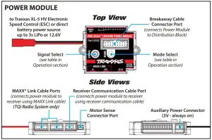
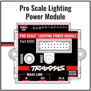
The Traxxas Pro Scale® Advanced Lighting Control System consists of two major electronic components: the Pro Scale Lighting Power Module (LPM) and the Pro Scale Lighting Distribution Block (LDB). The LPM installs on the chassis of the vehicle and performs as the voltage regulator and power supply for the lighting system. It also controls various lighting functions through the two buttons on the face of the module and communicates with the receiver in the model via the communication cable (or the optional included MAXX® Link cable for models equipped with a TQi radio system). The LDB mounts in the body of the vehicle and is the distribution hub for all the various wired lights in the body. Its main function is to direct power and instructions to each of the installed lights to operate features such as brake lights, tail lights, reverse lights, turn signals, and high/low beam lighting.There is only one rugged breakaway wiring connector between the LDB and the LPM for reliable lighting performance, plus it makes it easy to remove the body for vehicle service. The connector is designed to break away from the vehicle, without damage, if the body comes off the vehicle in a crash.There are lighting channels on the LPM which allow lighting installed on the chassis to be permanently connected and integrated into the system. This is helpful to install features such as rock lights, bumper lights, and other chassis-mounted accessory lighting.
Kit Contents
- Pro Scale Lighting Power Module
- Power module chassis mount
- Pro Scale Lighting Distribution Block
- Motor sense wire harness
- Breakaway cable (part of the distribution block)
- MAXX® Link cable (Data Link) (TQi Radio System only)
- Receiver communication cable
- 2.6x8mm button-head cap screw (2)
- 2.5x10mm countersunk cap screw (1)
- 2.5x12mm cap screw (1)
- 2.5x18mm cap screw (1)
- Zip ties (10)
- Silicone grease
Tools required
- 2.0mm hex wrench (part #3415, sold separately)
- Wire cutters (to trim zip ties)
- Small needle nose pliers
Overview
Each TRX-4® and TRX-6™ model has its own unique LED light kit package (lights and wiring) and Pro Scale Lighting Installation Kit (listed below, each sold separately). The included instructions cover installation of the mounting system and a wiring diagram specific to the model. If you have already installed aTraxxas LED light kit on your TRX-4 or TRX-6 model, the installed lights are compatible with the Pro Scale Advanced Lighting Control System, except for the Land Rover® Defender®, which requires a new LED light kit with additional lighting positions. Visit Traxxas.com/ProScaleLighting for additional information.
| Model Fitment | TRX-4 Sport |
TRX-4 Sport Equipped with Traxx™ |
Mercedes-Benz® G 500® |
Mercedes-Benz® G 63® |
Land Rover® Defender® |
Ford® Bronco® |
1979 Chevrolet® Blazer® |
1969 & 1972 Chevrolet® Blazer® Body |
| Vehicle Model Number | 82024-4 | 82034-4 | 82096-4 | 88096-4 | 82056-4 | 82046-4 | 82076-4 | 9111X 9112X |
| Installation Kit Part Number* | 8083** | 8083** | 8893** | 8893** | Included with 8095 LED Light Kit | 8032** | 8082** | 8091 |
| Compatible LED Light Kit(s) Part Number* | 8085, 8086, 8087, 8088 | LED Light Kit factory installed | 8899 | LED Light Kit factory installed | 8095† | 8036 | 8039 | 8090 |
- All LED light kits and installation kits sold separately. Install LED lights kit(s) prior to installation of the Pro Scale Advanced Lighting Control System.
- Includes additional amber and/or reverse lights (as required by model).
- Includes additional amber, fog, and reverse lights. LED Light Kit 8030 for Land Rover® Defender® is not compatible with the Pro Scale Lighting Power Module.
DISTRIBUTION BLOCK LED LIGHT HARNESS PORTS
Wiring connectors for the lights are labeled with numbers and/or colors.
|
Letter |
Description | Function |
| A | Reverse light harness |
Back up light LEDs when vehicle is put in reverse |
|
B |
Rear turn signal harness | Rear turn signal LEDs (if equipped) |
| C | Tail light harness |
Tail lights, brake lights, and rear integrated turn signal LEDs (if equipped) |
|
D |
Rear side marker harness | Rear side marker LEDs (if equipped) |
| E | Rear independent turn signal jumper |
Install jumper when using rear independent turn signals (separate amber LEDs); remove jumper when using rear integrated turn signals (single red LED for tail, stop, and turn) |
|
F |
Rear integrated turn signal jumper | Install jumper when using rear integrated turn signals (single red LED for tail, stop, and turn). Remove jumper when using rear independent turn signals (separate amber LEDs) |
| G | Head light assembly harness |
Headlights, front marker light LEDs, and side marker light LEDs |
|
H |
Front turn signal harness | Front turn signal light LEDs |
| K | Rear high brake light harness |
High brake light LEDs (if equipped) |
|
M |
Light bar high/low harness | LED light bar that typically mounts to the roof of the vehicle (if equipped) |
| N | Rock lights/scene lights assembly harness |
Accessory LED lighting that mounts to the vehicle body (if equipped) |
WIRING DIAGRAM
Visit Traxxas.com/ProScaleLighting for additional information about installing and connecting accessories such as auxiliary lighting (rock lights shown, part #8026X, sold separately) to the Pro Scale Lighting Module.
POWER MODULE INSTALLATION
Remove the 8028 LED lights power supply from the chassis (if installed). Install the Power Module mount on the chassis with the included 2.5x10mm countersunk cap screw; then, install the Lighting Power Module on the mount with the included 2.5x12mm (1) and 2.5x18mm (1) cap screws (Fig.1).

COMMUNICATION CABLES
Your Pro Scale Advanced Lighting Control System includes two communication cables: the Receiver Communication Cable and the optional MAXX® Link Cable. You can use the Receiver Communication Cable with any TRX-4 or TRX-6 model. The MAXX Link Cable is designed for use only with TRX-4 or TRX-6 models equipped with the TQi receiver. The 6511 Traxxas Link Wireless Module (sold separately) is required for Traxxas Link App functionality. Some models may require a software update for the TQi receiver via the Traxxas Link App for custom lighting controls and configurations. Only use one of the communication cables to connect the Lighting Power Module to the receiver. Do not use both cables together.
- Receiver Communication Cable

- MAXX® Link Cable
RECEIVER COMMUNICATION CABLE INSTALLATION
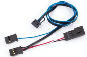
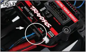
- Plug one end of the Receiver Communication Cable (Fig. 2) into the RX IN port on the Power Module (Fig. 3) (refer to the Wiring Diagram for more detail).
- Remove the 3x10mm counter-sunk cap screws (2) from the battery tray (Fig. 4). Lift up the battery tray and route the Receiver Communication Cable from the Power Module under the battery tray and to the receiver box (refer to the Wiring Diagram for more detail). Use a zip tie (included) to attach the wires. Reinstall and tighten the battery tray screws.Note: Be careful not to pinch or damage any of the wires under the battery tray.
- Remove the receiver box cover by removing the three 3x8mm button-head cap screws (Fig 5).
- Remove the wire clamp by removing the two 2.5x8mm cap screws (Fig 5).
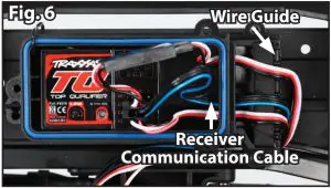
- Feed the loose end of the Receiver Communication Cable connector over the wire guide and into the receiver box. To make installation easier, unplug and remove a few of the existing wires from the receiver box. Note the locations of any unplugged wires. Use needle nose pliers to help grab the connectors and pull them through. Arrange all wires neatly between the wire guides in the receiver box (Fig. 6). The excess wire will be bundled inside the receiver box.
- Apply a bead of the included silicone grease to the wire clamp (Fig. 7).
- Reinstall the wire clamp and tighten the two 2.5x8mm cap screws securely (Fig. 8).
- Unplug the electronic speed control (ESC) from the receiver (channel 2).
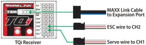
- Plug the communication cable into the receiver (Fig. 9): the black connector with the single blue wire plugs into one of the channel 1 ports; the female black connector with the 3 black wires plugs into the channel 2 port. Now, plug the black male connector (white, red, black servo cable) from the ESC into the black female connector (white, red, black servo cable) on the communication cable (refer to the Wiring Diagram for more detail). Leave the steering servo cable plugged into the other channel 1 port. 10. Make sure the blue o-ring gasket is properly seated in the groove in the receiver box so that the cover will not pinch it or damage it in any way.
- Reinstall the cover on the receiver box and tighten the three 3x8mm button-head cap screws securely. Inspect the cover to make sure that the O-ring seal is not visible.
- Use the supplied zip ties to bundle the wires neatly and attach them to the vehicle as needed so that loose wires will not become entangled with moving parts.
MOTOR SENSE WIRING HARNESS INSTALLATION
- Unplug the red and black motor wires (bullet connectors) from the ESC. Plug the bullet connectors from the motor and the ESC into the motor sense wiring harness (red to red and black to black) (Fig. 10). Plug the harness connector into the Motor Sensor port on the power module (refer to the Wiring Diagram for more detail).
- Use the supplied zip ties to bundle the wires neatly and attach them to the vehicle as needed so that loose wires will not become entangled with moving parts.
- Plug the breakaway cable from the distribution block into the connector on top of the Power Module before installing the vehicle body (Fig. 11).
OPTIONAL MAXX LINK CABLE WIRING
Use the optional included MAXX® Link Cable with any Traxxas TRX-4 and TRX-6 model that includes a TQi radio system to connect the Lighting Power Module to the receiver.The MAXX Link Cable is designed to work with the Traxxas Link™ Wireless Module (part #6511, sold separately) to provide Traxxas Link App functionality for custom lighting controls and configurations.
Some models may require a software update for the TQi receiver via the Traxxas Link App (Traxxas Link Wireless Module required).
Plug the MAXX Link cable into the MAXX Link IN port on the Lighting Power Module. Use the same wire routing from the Lighting Power Module and into the receiver box as shown in the Receiver Communication Cable Installation instructions. Plug the loose end of the cable into the expansion port on the receiver.
WIRING DIAGRAM WITH HIGH-OUTPUT EXTERNAL BEC (part #2262, sold separately)
Important: To prevent possible damage to the electronics while using an external BEC, do not connect both the MAXX Link Cable and Receiver Communication Cable to the Lighting Power Module at the same time.
OPERATION
Headlights Mode SelectionUse the Mode button on the Pro Scale Lighting Power Module to cycle through the different lighting modes (from Low Beam Mode to High Beam Mode to Daytime Mode).
Hazard LightsUse the Signal button on the Pro Scale Lighting Power Module to turn the hazard lights on or off.
Turn SignalsThe turn signals are activated by default. To deactivate the turn signals, press and release the Signal button on the Pro Scale Lighting Power Module two times quickly. Both left turn signal LEDs will blink once, and then both right turn signals LEDs will blink once to indicate that the turn signals are deactivated.
To reactivate the turn signals: Press and release the Signal button two times again quickly. Both left turn signal LEDs will blink twice, and then both right turn signals LEDs will blink twice to indicate that the turn signals are activated.
Turn Signal Operation:With the vehicle stopped, turn the steering wheel on the transmitter (left or right) to turn on the LEDs. The turn signal LEDs will continue to flash while the steering wheel is turned in this same direction or remains centered. Turn the steering wheel in the opposite direction to cancel the turn signal.
| Mode | Selection | Action |
| Low Beam Headlights | Default | |
| High Beam Headlights | Press and release Mode | |
| Daytime Headlights (off) | Press and release Mode once again |
| Signal | Selection | Action |
| Hazard Lights On | Press and release Signal once | |
| Hazard Lights Off | Press and release Signal once again | |
| Deactivate Turn Signals | Press and release Signal 2x quickly | |
| Activate Turn Signals | Press and release Signal 2x quickly again |
WARRANTY
Warranty InformationTraxxas electronic components are warranted to be free from defects in materials and workmanship for a period of 30 days from the date of purchase.
Limitations: Any and all warranty coverage does not cover replacement of parts and components damaged by abuse, neglect, improper or unreasonable use, crash damage, water or excessive moisture, chemical damage, improper or infrequent maintenance, accident, unauthorized alteration or modification or items that are considered consumable.Traxxas will not pay for the cost of shipping or transportation of a defective component to us.
Traxxas Lifetime Electronics WarrantyAfter the expiration date of the warranty period, Traxxas will repair electronic components for a flat rate. Please visit Traxxas.com/support for a current schedule of warranty costs and fees. The covered repairs are limited to non-mechanical components that have NOT been subjected to abuse, misuse, or neglect. Products damaged by intentional abuse, misuse, or neglect may be subject to additional charges. Traxxas liability, in no case, shall be greater than the actual purchase price of this product.For replacement, product must be returned in brand new condition, with packaging and itemized sales receipt.
Download and install the latest firmware updates, change the module settings, and gain access to additional functions using the Traxxas Link App (available in the Apple App StoreSM or on Google Play™).The TQi transmitter with the Traxxas Link Wireless Module (part #6511, sold separately) are required.
This device complies with FCC Part 15 & IC RSS-210 rules subject to the following conditions: 1) This device may not cause harmful interference, and 2) This device must accept all interference received, including interference that may cause undesired operation.
For patent and patent-pending information, please visit Traxxas.com/pat
report this adApp Store is a service mark of Apple Inc. Google Play is a trademark of Google Inc.Mercedes-Benz®, G 500®, and G 63® are trademarks of Mercedes-Benz/Daimler AG.Land Rover® and Defender® are trademarks of Jaguar Land Rover Limited.Ford® and Bronco® are trademarks of Ford Motor Company.Chevrolet® and Blazer® are trademarks of General Motors.All copyrights and trademarks are used by Traxxas under license.
Customer Support
Traxxas, 6250 Traxxas Way, McKinney, TX 75070,Phone: 972-549-3000,Fax: 972-549-3011,e-mail: [email protected]
References
[xyz-ips snippet=”download-snippet”]