
Trimline Fires Next Generation Electric Fires User Manual
[email protected]www.trimlinefires.com
IMPORTANT INFORMATION
- WARNING: In order to avoid overheating, do not cover the heater or air vents located on the appliance.
- CAUTION: Some parts of this product can become very hot and cause burns.
- This appliance is intended for domestic household use only and should not be used for any other purpose or in any other application, such as for non-domestic use or in a commercial environment.
- If the supply cord is damaged, it must be replaced by the manufacturer, its service agent or similarly qualified persons in order to avoid a hazard.
- Particular attention has to be given where children and vulnerable people are present.
- Children of less than 3 years should be kept away from the products unless continuous supervised.
- The heater must not be located immediately below a socket-outlet.
- Do not use this heater in the immediate surroundings of a bath, a shower or a swimming pool.
- The plug must remain easily accessible after installation of the appliance.
- As a safety precaution, the heating element of this appliance will automatically turn off once temperature sensor has detected the room temperature has reached 35 °C.
- CAUTION: In order to avoid a hazard due to inadvertent resetting of the thermal cut- out, this appliance must not be supplied through an external switching device, such as a timer, or connected to a circuit that is regularly switched on and off by the utility.
- Keep the appliance away at least 1 meter from furniture, curtains or other combustible material when in use.
- This appliance is intended for indoor use only and is not suitable for outdoor operation.
- Do not use the appliance in rooms with explosive gas (e.g. petrol) or while using inflammable glue or solvent (e.g. when gluing or varnishing parquet floors, PVC etc.).
- Do not insert any objects into the appliance.
- Do not place the power cord under a rug.
- Do not operate the appliance near flammable materials or fire.
- Switch off and unplug the appliance from the mains socket when not in use or before cleaning and maintenance.
- Do not clean the appliance with abrasive cleaners.
- Parts of this appliance become hot whilst in operation and under no circumstances should persons under the age of 12 be left alone with the product when it is in operation unless a suitable fireguard is used to protect them against the possibility of coming into direct contact with the appliance.
REMOTE CONTROL BATTERY INFORMATION
- Only adults should handle the batteries. Do not allow a child to use the remote control unless the battery cover is securely attached.
- The battery type used in this remote control is 2 x AAA 1.5V battery. The batteries are located internally and are readily accessible.
- Remove the cover on the back of the remote control to remove the batteries.
- Do not mix battery types or new and used batteries.
- Batteries are to be inserted with the correct polarity.
- Batteries must be disposed of safely at your local recycling point.
BATTERIES ARE DANGEROUS IF SWALLOWED!
NOTE: For illustrative purposes this guide uses the Trimline 90E appliance to demonstrate points. Although other models may differ in size/proportion, the overall aesthetic, build and functionality remain the same.
USER INSTRUCTIONS – OPERATION
This appliance can be operated manually (with limited, basic functions only) or by remote control.
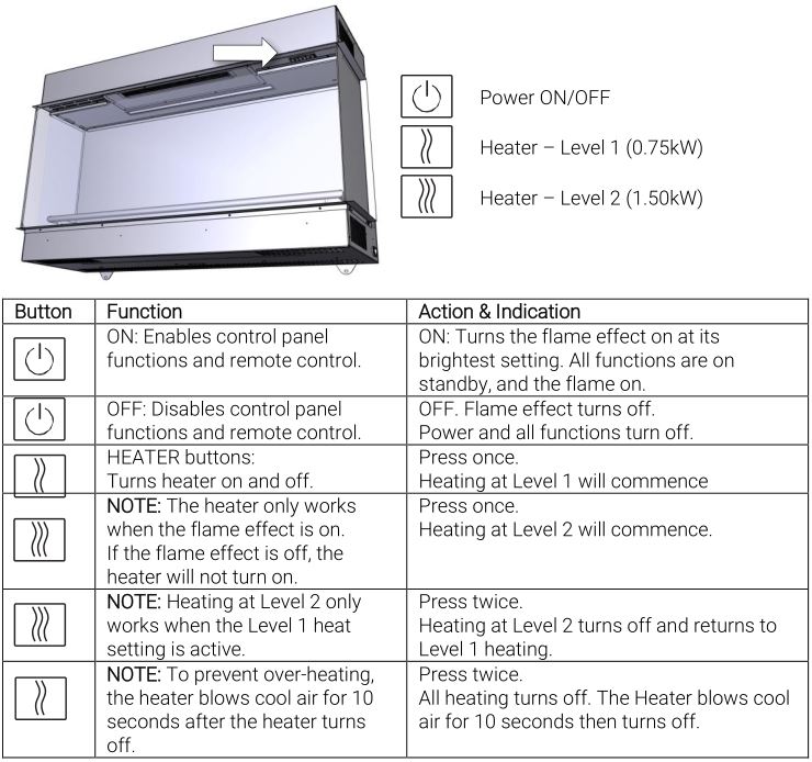
Manual ControlEnsure that the appliance is turned on at the mains. Locate the manual operating buttons situated to the right side of the heater outlet.
Remote Control
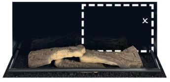
NOTE: The optimum distance for operating the remote control is 1.5m from the appliance. Standing in front of the appliance, looking at the flame screen, the ‘x’ is where the infra-red receiver is located. This is the optimum spot to point the handset. Whilst standing away from the appliance, pointing anywhere within the dashed box will still reach the receiver. Pointing anywhere outside of the green box may result in poor signal receipt and non-operation.
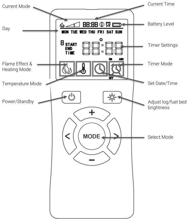
When the appliance is in standby mode, the remote control will show the current time, battery level and operating mode at the top of the screen. The appliance can be turned on by pressing the POWER/STANDBY button on the remote control. This will turn on the flame effect only. The desired operating mode can then be selected.
Flame Effect and Heating Mode
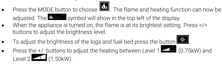
Temperature Mode (Thermostatic)
In temperature mode, a specific temperature limit can be set so that the appliance automatically turns off the heater when the room temperature reaches that limit, after which the appliance will continue to operate in flame effect mode only. The temperature range that can be set is: Fahrenheit 65-95°F or Centigrade 18-35°C

NOTE: when appliance is next turned on, the temperature setting will be the same as the previous time the appliance was used.
When the appliance is in standby mode, the remote control will show the current time, battery level and operating mode at the top of the screen.
Timer ModeIn timer mode the appliance can be set to operate and turn off at a set of pre- programmed times.
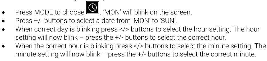
Timer Mode – Setting the Day/Time
Timer Mode – Setting the Programme

NOTE: If Timer Mode has been programmed incorrectly, e.g. the END time is earlier than the START time, ![]() will show on the screen.
will show on the screen.
NOTE: When Timer Mode is on, the ![]() icon will show on the top of the screen.
icon will show on the top of the screen.
NOTE: When the battery power is low the battery log will blink on the screen. You should insert a new battery. The original settings can remain programmed for up to 30 minutes after the battery is taken out of the remote-control handset.
CLEANING & MAINTENANCE
- Ensure that the appliance is completely cooled down and disconnected from the mains supply before undertaking any cleaning or maintenance work.
- Do not use abrasive cleaners.
- Use a lightly damp cloth to wipe clean the glass panels and metal surfaces.
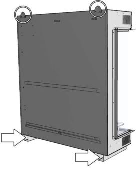
- Keep the air inlets clear and free from dust and debris. Regular cleaning is advised to prevent performance problems. Clean the areas around the air inlets (indicated with arrows below) with a soft cloth/duster or vacuum cleaner.
INSTALLATION
Carefully unpack the appliance and dispose of the packaging responsibly. Keep plastic wrapping away from children.
Locating the Appliance
This appliance can be installed into an existing chimney breast or a purpose-built studwork chimney.If installing into an existing open chimney, precautions must be taken to avoid excessive drafts, moisture or debris that may fall onto the appliance.The appliance should be installed close to a mains socket. The socket must be easily accessible to allow disconnection after installation.When building a studwork chimney breast ensure that the appliance does not bear the weight of the finished wall. Use a header if required.Allow for the finished face of the chimney breast when considering the depth of the structure.
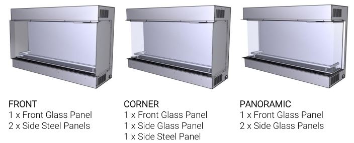
Preparing the ApplianceThe appliance can be modified to offer 3 different styles of fire:
When unboxed, the appliance comes with both side steel panels fitted in place. Regardless of the desired style of fire, the steel side panels must first be removed to gain access to the accessories contained within the fire.
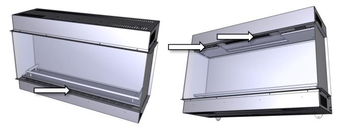
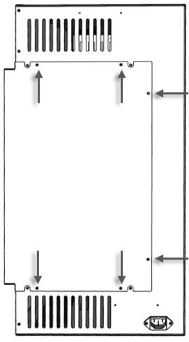
STEP 1Locate and remove the four screws indicated with arrows. Keep the screws safe for future use. Carefully remove the steel plate and set aside.Repeat the process on the other side of the appliance.
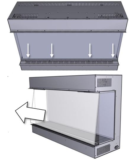
STEP 2 Next, locate and remove the four screws securing the rail at the bottom of the front glass panel. Remove the rail.
STEP 3Remove the front glass panel gently gripping at both sides and carefully pulling forwards from the bottom edge. Once removed, place the glass in a secure location where it cannot be damaged. Continue to remove both pieces of side glass by gently pulling towards you. Place these in a secure location where they cannot be damaged.
STEP 4Remove the packaged accessories from inside the fire. You should find the following components:
1 x Log retaining bar1 x Appliance hanging rail1 x Power lead1 x Bag of screws2 x Sets of steel side glass finishing edges4 x Short fireplace fixing brackets1 x Remote control handset (with batteries)2 x Feet (Trimline 75E only)
Before proceeding it is advised that you test the appliance for operation before continuing with installation
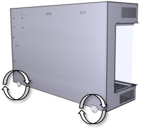
STEP 5a Locate the two securing brackets located on the rear of the appliance. Unscrew both, rotate 180 degrees and re-screw onto the appliance as shown in the image.
STEP 5b ( Trimline 75E E only)When fitting the Trimline 75E at hearth level into a fireplace mantel, remove and locate the fixing brackets mentioned above and fit to the top edge of the appliance. Next, fit the two feet to the underside of the appliance using the 12 screws provided.

STEP 6Fix the appliance to the wall using the hanging rail supplied. Use appropriate fixings for the wall type you are installing to. Ensure that the bracket is fitted level. Lift the appliance and offer it towards the bracket, aligning the 3 tabs with the threeslots on the rear of the appliance. Once fitted, secure the appliance to the wall with the two securing brackets on the rear of the appliance using appropriate fixings for the wall type.
NOTE: The hanging rail is not required when fitting the Trimline 75E at hearth level.
STEP 7Arrange the ceramic fuel. See Appendix 1 for guidance.
NOTE: Before proceeding it is advised that you test the appliance for operation before continuing with installation. Pay particular attention to the arrangement of vermiculite gravel around the contact points with the ceramic logs. Experiment with small gaps in the gravel to allow the flickering orange light below to shine through.
STEP 8Replace the glass referring to the process detailed in Steps 2 & 3. If you are using a FRONT (front glass only) or CORNER (front and 1 side glass only) you do not need to replace the side glass where a steel side panel will be replaced. To replace the steel side panel on these models please refer to the process detailed in Step 1.For glass sided appliances (PANORAMIC and CORNER) you may want to fit the steel glass finishing edges around the side glass panels. These are fitted using the screws from the steel side panels.

STEP 9Build studwork chimney breast. When building a studwork chimney breast ensure that the appliance does not bear the weight of the finished wall. Use a header if required. Allow for the finished face of the chimney breast when considering the depth of the structure. Ensure that the power lead is connected to the appliance and to a mains socket that is fully accessible at all times.
IMPORTANT: W hen building the stud framework, ensure that there is a clearance gap around all sides of the appliance of at least 60mm to allow for critical airflow.IMPORTANT: Do not seal the appliance into the chimney breast as this can impact upon the air flow. When boarding to the appliance, leave a 5mm gap. This gap will be covered by the glass finishing edges.
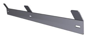
Shelf/Plinth FittingWhen installing a floating MDF or Timber shelf/plinth use the long fireplace fixing bracket and two short fireplace fixing brackets. These are screwed to the appliance and can be adjusted in height to suite different thicknesses of material.
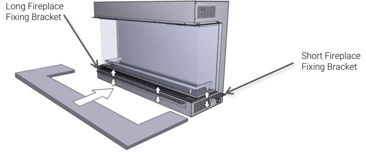
Offer the shelf up to the appliance, sliding onto the fireplace fixing brackets. Secure the shelf by screwing through the holes on the fireplace fixing brackets into the underside of the shelf. Ensure that the screws are the correct size to avoid penetration of the top surface of the shelf. For heavier floating shelves/plinths, such as granite or limestone, refer to the fitting instructions that are supplied with it.
Mantel/Beam FittingWhen installing an MDF or timber mantel or beam, use two short fireplace fixing brackets. Depending on the type of mantel or beam being used, the brackets can be rotated to use either the slots of holes to fix it to the sides of the appliance. Once fitted, offer up the mantel or beam and screw through the brackets into the underside, being careful to use screws that are the correct length.

TROUBLESHOOTING
No power to the appliance
- Check of the appliance is connected to mains supply and switched on
- Check the remote-control batteries
- Check the consumer unit breaker has not tripped
- Check the fuse in the plug
- Confirm the output from the socket by plugging in a different appliance
Flame effect working but no heat
- Determine if Temperature Mode is activated and that the set temperature is higher than the current room temperature
- Check for blockages/obstructions around air intakes as the safety cut-out may have activated. Clear any blockages/obstructions
- Switch appliance off at the mains, wait for 1 minute then switch back on. These actions should reset the safety feature
No flame movement or poor flame movement
- Check that the fan is running below the flame by listening for an audible hum, prior to turning on heat
- Allow for a small period of time (approximately 5 minutes) for the appliance to warm up sufficiently
Noise during operation
- It is normal for some noise during operation due to moving mechanical components and air movement
- Check that the glass has been secured properly and does not sit loose
- Check all trims and other removable/decorative components for ill-fitting that could be causing vibrations
- Check for any foreign objects deposited through the air vents
Remote control not working
- Refer back to check that the appliance has power
- Check the batteries in the handset are in working order and show no signs of corrosion or damage
- Check that the remote is pointed correctly at the appliance. See page 5 for more information
Burning smell coming from appliance
- Check for a build-up of dust or obstruction on the air vents and clear if necessary
- Check for any foreign objects or liquids deposited through the air vents
- Do not operate the appliance if the smell persists.
APPENDIX 1
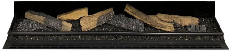
Trimline 75E Fuel Bed Layout SuggestionDistribute the vermiculite gravel evenly around the white plastic fuel bed. Arrange the logs on top of the vermiculite. Finish by positioning the log retaining rail around the logs. Experiment with creating small gaps in the vermiculite to allow illumination from below, creating a ‘glowing ember’ effect.
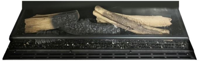
Trimline 90E Fuel Bed Layout SuggestionDistribute the vermiculite gravel evenly around the white plastic fuel bed. Arrange the logs on top of the vermiculite. Finish by positioning the log retaining rail around the logs. Experiment with creating small gaps in the vermiculite to allow illumination from below, creating a ‘glowing ember’ effect.
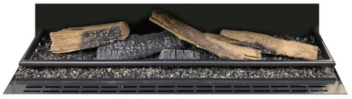
Trimline 140E Fuel Bed Layout SuggestionDistribute the vermiculite gravel evenly around the white plastic fuel bed. Arrange the logs on top of the vermiculite. Finish by positioning the log retaining rail around the logs. Experiment with creating small gaps in the vermiculite to allow illumination from below, creating a ‘glowing ember’ effect.
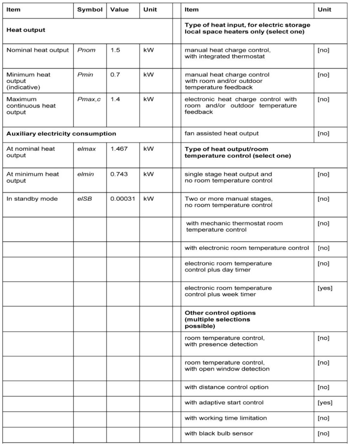
TECHNICAL INFORMATION
Contact details:
Trimline Fires is powered by thermoCet International B.V.Laagerfseweg 313931 PC Woudenberg,The Netherlands+31-(0)23-5833050[email protected]www.trimlinefires.com
Trimline Fires Next Generation Electric Fires User Manual – Trimline Fires Next Generation Electric Fires User Manual –
[xyz-ips snippet=”download-snippet”]