![]()
ALL BANDCOMMUNICATIONSRECEIVER
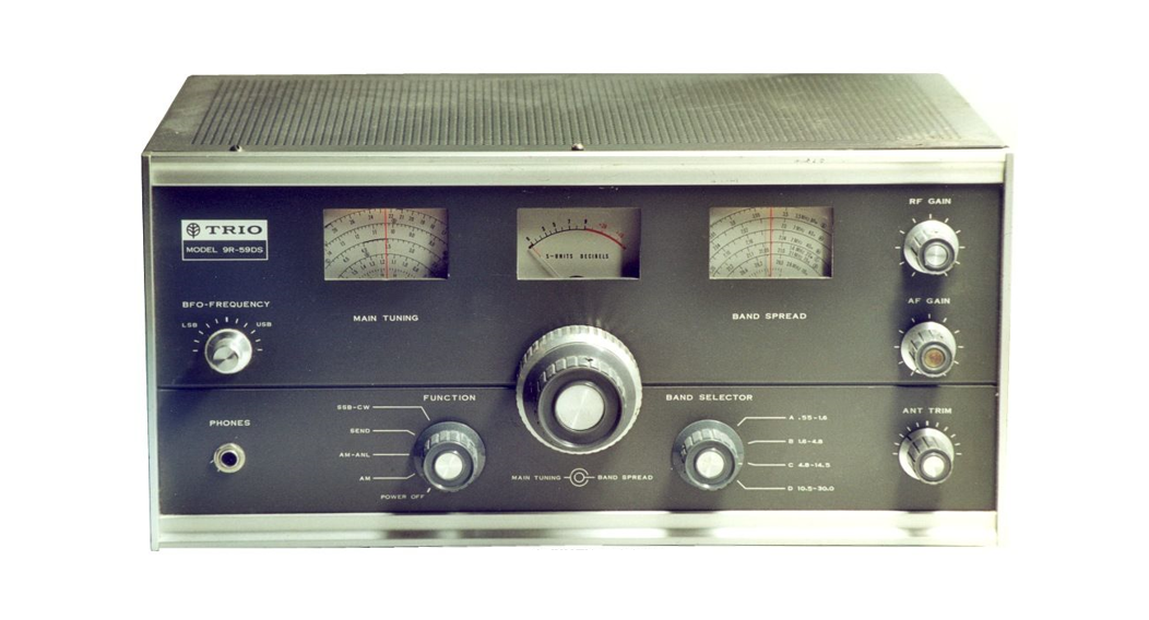
9R-59DS
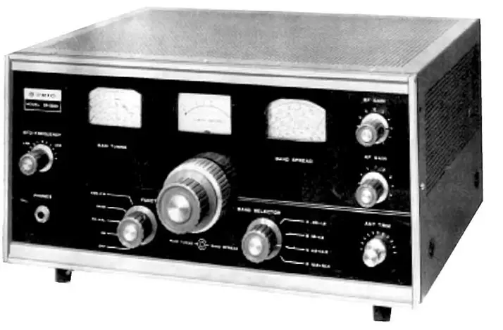
TRIO 9R-590S
TRIO ELECTRONICS INC., makers of the finest professional testing equipment and communication apparatus, proudly presents the 9R59DS, a new, de-luxe receiver for today’s amateur operator, as well as the discerning shortwave listener. TRIO’S most advanced engineering techniques and design are incorporated into this all-purpose receiver which has many superior features found only in the most expensive communications equipment.
SPECIAL FEATURES
- Main tuning and Band Spread readings are easily made on these easy-to-read separate The anti-backlash mechanism is smooth and sure. It provides close calibration accuracy and makes tuning a real pleasure.
- The receiver provides continuous coverage from 550 kHz to 30 MHz. The band spread tuning, with the direct reading dial, is available on amateur bands.
- Superb selectivity, heretofore unattainable with ordinary IF Transformers, is achieved through the use of a mechanical filter.
- One RF and two audio stages of amplification ensure high sensitivity and selectivity.
- Unusually stable operation is obtained through special design and shielding.
- Clear SSB reception is achieved through the use of a Product Detector.
- A large easy-to-read S meter provides accurate S readings at all times, including during CW and SSB reception.
- Pre-mounted and pre-aligned printed board circuits are utilized in the front end. This permits successful kit-form assembly even by beginners.
- The ANL circuit (Automatic Noise Limiter) effectively limits interference from pulse-type noise.
- The receiver is equipped with a standby switch, enabling it to be used with any transmitter, or it can be used alone for listening purposes.
- A phone jack is provided so that the receiver may be operated late at night without disturbing others.
- An antenna trimmer ensures optimum sensitivity on all bands.
- Bandspread on the 3.5 MHz band covers the 500 kHz between 3.5 and 4.0 MHz, enabling the use of this receiver in conjunction with a separate converter.
- A dial calibrating circuit can be readily
DESCRIPTION OF CIRCUITS
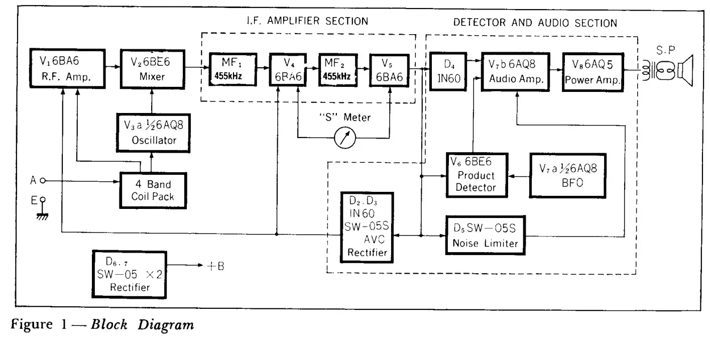
As shown in Figure 1, the 9R-59DS is a 550 kHz — 30 MHz continuous coverage superheterodyne receiver employing one stage of RF and two stages of Intermediate Frequency amplification. The following is a simple explanation of the various circuit functions and features.
RF AMPLIFIER CIRCUIT
A remote cut-off characteristic 6BA6 is employed in the RF amplifier stage. In designing the RF tuning and amplifier circuit, special emphasis was placed on obtaining good selectivity and sufficient amplification for improved signal-to-noise ratio, as well as good image ratio. The 47-ohm resistor in the lead to GI prevents oscillation and ensures stable RF amplification. AVC voltage in parallel fed to the cathode bias of the controlled tubes, the RE’ and IF amplifiers. The main Gain Control also varies the bias of the receiver’s front end. AVC is not available for SSB and CW reception.
OSCILLATOR
The performance stability of a receiver is determined to a great extent by the stableness of the local oscillator. Thus, a triode oscillator with low inter-electrode capacity is utilized here in a Hartley circuit, which is preferably used in all-band receivers because of its stable oscillation over a wide frequency range.
Frequency drift is practically nil. This is true even after the receiver has been left in a standby position during transmission intervals of amateur communication, as oscillation is maintained at all times. Another contributing factor is a new improved core in the oscillation coil. A plate reaction coil is used to maintain stable oscillation in the range above 20 MHz at which high frequencies, oscillation instability is prone to be encountered with tapped coil oscillators due to loss in conversion gain. The 68-ohm resistor between the coil and G1 is inserted to prevent over-oscillation and parasitic oscillation at the maximum receivable frequency.
MIXER
Pulling, that is, a change in Oscillator frequency caused by tuning of the mixer grid circuit is normally a formidable problem encountered in SSB and CW reception. This problem has been eliminated in this receiver by special attention to separate the oscillator and mixer circuits from any possibility of undesirable coupling. A small capacitance is utilized to feed the oscillator signal to the mixer circuit. Moreover, an independent 6BE6 is used as a grid-excited mixer to attain high conversion efficiency and low mixer tube noise.
The 150PF capacitor and the 1M ohm resistor leading to G3 achieves protection of the mixer tube against overload peaks. AVC is not applied to this stage as the receiver is designed primarily for sensitivity and stability.
I F AMPLIFIER CIRCUIT
The IF Amplifier circuit has two main functions. The first is the amplification of the intermediate frequency signal, and the second is to separate closely adjacent signals. The first function is achieved with two stages of 6BA6 amplification, while the second is achieved through the use of a mechanical filter.
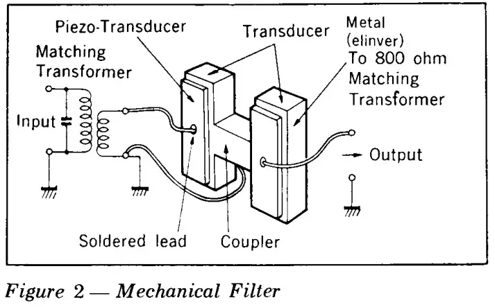
The construction and operation of the mechanical filter differ from ordinary LC-operated IF transformers. The IF input signal is first sent through a 455 kHz mechanical resonant circuit which serves as an ideal filter because of its sharp selectivity and frequency-resonance curve. Details of the mechanical filter are shown in Figure 2.
The IF stages, to which AVC voltage is fed, also ensure automatic volume control.
S-METER CIRCUIT
Adopted here is a stable system in which a bridge circuit is formed on the cathode side of the two IF amplifier tubes. GI of the first stage is grounded through a resistor but AVC voltage which is in direct ratio to signal intensity is applied to G1 of the second stage. This results in an imbalance between the two IF tubes, and the resultant current flow is used to operate the S-meter.
AVC CIRCUIT
A half-wave voltage doubler rectifier is used in the AVC circuit. Its advantages are superb sensitivity to signal intensity fluctuations, a completely independent AVC system that permits operation during SSB reception, and smooth adjustment of receiver gain. It also enables receiver standby during transmission by feeding C bias to the AVC circuit from a remote terminal supply.
ANL CIRCUIT
A silicon diode S-1.5-02 is used in an effective Automatic Noise limiter circuit. Pulse-type RF interferences cause a cut-off of the diode operation, resulting in the elimination of audio noise at the diode output, thus, functioning as a very effective ANL circuit.
PRODUCT DETECTOR CIRCUIT
Unlike AM detection, SSB and CW detection requires the utilization of the nonlinear curve. Although there are various detector circuit schemes to accomplish this, adopted here is a 6BE6 product detector which has proved to be most efficient and widely used.
Mixing occurs within the 6BE6 between the SSB signal and the BFO carrier which are fed to its respective grids, resulting in demodulation. It is necessary that the BFO carrier frequency is identical to the suppression carrier frequency of the transmitter.
BFO CIRCUIT
This circuit which enables SSB-CW operation requires a very stable oscillator so a tuned grid type has been adopted. BFO pitch is achieved through a front panel controlled midget variable condenser.
DETECTOR AND AUDIO AMPLIFIER CIRCUIT
Detection is achieved by the use of a diode detector. One-half of a 6AQ8 is used for first-stage audio amplification. Second stage audio amplification is achieved by a 6AQ5. A decoupling circuit is used in the plate circuit to eliminate hum.
POWER OUTPUT AND RECTIFIER CIRCUIT
A single 6AQ5 provides a maximum power output of 1.5 watts for speaker operation. Full-wave rectification in the power supply is achieved by the use of two silicon diodes. The local oscillator B plus plate supply voltage is separated from the B plate supply to the IF and AF stages. This minimizes fluctuation of the oscillator plate voltage even when the IF stage B supply voltages may fluctuate over a wide range during adjustment of the RF Gain Control.
TERMINAL CONNECTIONS
- ANTENNA
It is often said that a good antenna is more effective than a single-stage of RF amplification. In a communications receiver, especially, the choice of the antenna determines whether you will get 100% performance from your receiver or not. Begin, therefore, by erecting a good antenna.
a) Inverted L antennaAn Inverted L antenna is the easiest to erect and is quite effective, not for any single band, but generally for the entire short wave range of frequencies. A 1.2 to 1.6 mm wire, either twisted or solid, will do, and it should be erected as high as possible. Each end of the antenna wire should be terminated by insulators, and care should be taken to keep the lead-in wire away from the roof or a tree. Connect the lead-in to terminal A, and a good ground to terminal E.
b) Doublet AntennaMost amateur radio stations use a single antenna- na both for transmission and reception. An efficient transmitting antenna may be considered a good receiving antenna. Since the doublet antenna is also easy to erect, it is in wide use among ham operators.
The overall length of a doublet antenna can be determined by using the following formula.
L (Length in feet) = 468/Frequency in Mega Hertzes
For example, the overall length of a doublet antenna for use in the 7 MHz amateur bands would be as follows;468/7= 66.8 feet
Since the overall length is 66.8 feet, each element on both sides of the center insulator would be 33.4 feet. A coaxial cable such as a 3C-2V is connected to the elements at the center and brought into the receiver. Fig. 3 (a) shows such an antenna that is widely used.
Fig. 3 (b) illustrates the simplest form of a doublet antenna which is made of a necessary
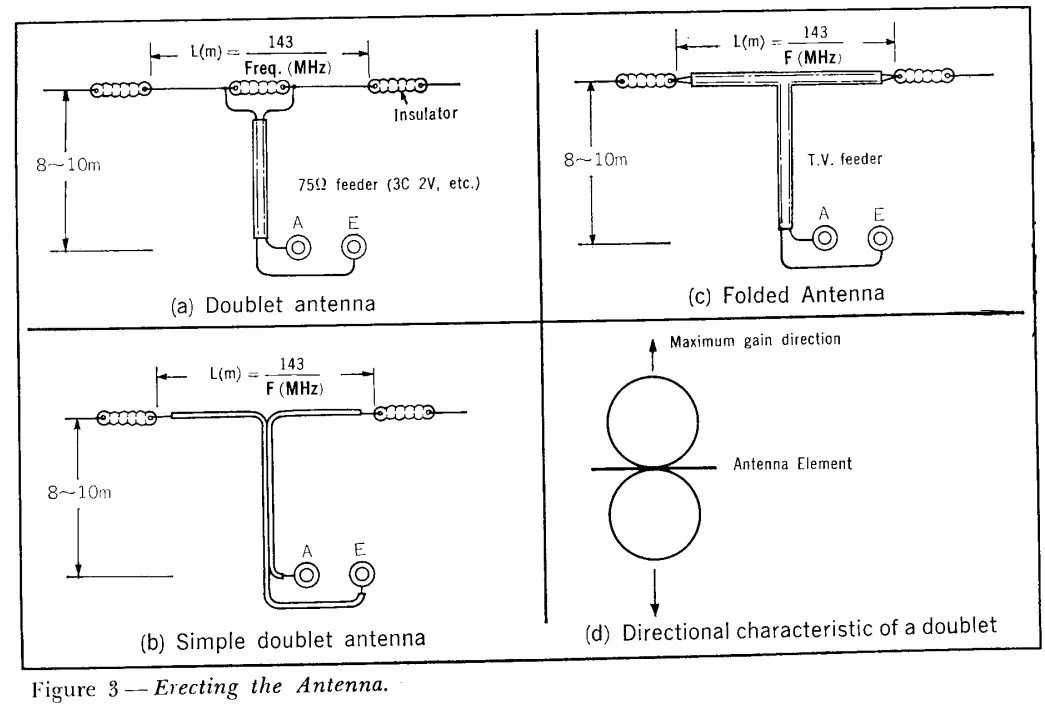
length of a twin-lead type, vinyl chloride-coated cord for electric lighting. Fig. 3 (c) shows a “folded dipole” type that can be made from a TV feeder. It is light and provides a wider band coverage than an ordinary doublet.
Since the doublet antenna displays directional properties, it should be oriented for maximum gain from the desired direction as shown in Fig.3 (d).
- SPEAKERUse a permanent magnet dynamic speaker without a power transformer. Connect it to the 8 or 4-ohm output terminals of the receiver depending on the impedance of the available speaker. A 16-ohm speaker should be connected to the 8-ohm terminal. Headphones should be connected to the 8-ohm terminal to disable the speaker.
- HEADPHONESAlthough low-impedance magnetic head-phones are preferable, other types can also be used.
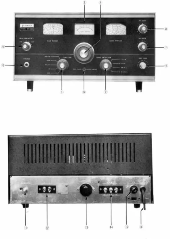
DESCRIPTION OF CONTROLS
- FUNCTION — function switchAt various positions, this switch controls the functions of the receiver as follows:OFF — Turns off the AC power source to the receiver.AM — Receiver is set for reception of Amateur Bands, broadcast band, and short wave overseas broadcasts.AM-ANL — Switch to this position when pulse-type interference such as static or automobile ignition noise hampers reception.SEND — This switches off B voltage to the RI’ Amplifier stage and temporarily renders the receiver inoperative for transmission standby.SSB-CW — Receiver is set for SSB and CW reception.
- BAND SELECTOR (BAND SELECTOR SWITCH)This is the Band Selector Switch which enables the selection of four different bands at positions A, B, C, and D.
- MAIN TUNING (Main Tuning Knob)This is the main tuning knob. Dial calibration is accurate when the Band Spread indicator is set at 100.
- BAND SPREADWhen the Main tuning is set from A to E, the Amateur Band is spread out over the entire face of the dial. This permits extremely fine-tuning.
- ANT TRIM (Antenna Trimmer)Adjust this knob for maximum deflection of the S meter while actually receiving a signal with the antenna connected to the receiver. Be sure to readjust this trimmer for optimum reception whenever a band is changed.
- S-METERThe meter indicator swings in direct proportion to signal intensity. It rests at 0 to 1 when nothing is being received and there is no static.
- AF GAIN (Volume Control)Volume is increased when the knob is turned in a clockwise direction.
- RF GAIN (Sensitivity Control)Set this control at the full clockwise direction for normal reception, except when receiving especially strong local stations to prevent overloading.
- BFO-FREQUENCY (BFO Pitch Control)Use this control when receiving CW or SSB stations.
- PHONES (Headphone Jack)Use this jack to switch out the speaker and receive through the headphones.
 DESCRIPTION OF REAR CHASSIS CONTROLS AND TERMINALS
 - ZERO-ADJ (S-meter Zero Set Control)Set this control so that the S-Meter indicator reads 0 with the antenna left unconnected.
- A-E TERMINALSThese are the terminals for connecting the antenna and ground.
- REMOTEThese are used when operating the receiver with any transmitter. They are not used when the receiver alone is operated.
- OUTPUT (Output terminals)These are the audio output terminals, available in 4 ohms and 8-ohm impedance matches. Use the 8-ohm terminal when connecting the SP-5D speaker.
- FUSEBe sure to replace a blown fuse with another rated at two amperes. Avoid using wire or higher rating fuses to ensure the protection of your receiver.
- AC LINE CORD
 DESCRIPTION OF REAR CHASSIS CONTROLS AND TERMINALS
INSTRUCTIONS
- ZERO ADJUSTMENT OF S-METERFirst, bring the receiver into operating condition. Set the IF Gain control to maximum and short the Antenna and Ground Terminals A and E. Adjust the rear chassis ZERO-ADJ control for 0 reading of the S meter.
- ORDINARY RECEPTIONFor ordinary medium or short wave reception, the various front panel controls should be set as follows:FUNCTION — to AM.BAND SELECTOR — to the desired frequency band.MAIN TUNING — to receive the desired broadcast. Tune for maximum deflection of the S Meter.BAND SPREAD — so that indicator reads 100° on the dial.For short wave reception, set the MAIN TUNING POINTER at a frequency a little higher than the desired one. Then manipulate the BAND SPREAD knob for ease in tuning.RF GAIN (Sensitivity) — in accordance with the strength of the incoming signal. Turning clockwise increases receiver sensitivity.AF GAIN (Volume Control) — for desired volume level.AM-ANL (Noise Limiter) — when pulse-type interference disturbs reception.
- FOR SSA RECEPTIONSet controls as follows:FUNCTION — to SSB-CW.BFO FREQUENCY — for 3.5 MHz to 7 MHz reception set the control to LSB position. For 14 MHz and higher frequency range, set the control to USB.For reception of commercial SSB stations, always set the control to LSB.BAND SPREAD — Tuning is the same as for AM. However, this knob should always be used for SSB tuning. It should be turned slowly until the desired station comes into resonance which will result in smooth demodulation.RF GAIN — Setting this control for the minimum sensitivity required for the reception of the desired SSB signal will assure smooth demodulation.AF GAIN — to the extreme clockwise position. The above settings should enable normal SSB reception. However, when difficulty is encountered in demodulation, switch BFO and manipulate the BFO FREQUENCY control from LSB TO USB, and vice versa. This should be done only after you have ascertained that the desired SSB signal is accurately tuned in. It should be remembered that any adjustment of the BFO FREQUENCY should be slight and limited only to improve upon delicate BAND SPREAD tuning.
- CW OPERATION
The control settings for the reception of code signals are essentially the same as for SSB. However, there is no necessity of setting BFO to one position or another for certain bands. Just adjust the BFO trimmer for desired pitch.
- ANT TRIM (Antenna Trimmer)
This control enables optimum tracking on all bands, that is, it matches the receiver to the antenna at all frequencies. Adjust ANT TRIM control for maximum deflection of the S meter after the desired signal has been tuned in.
AUXILIARY CIRCUITS WHICH MAY BE ADDED TO YOUR RECEIVER
The following auxiliary circuits may be added to your receiver if so desired. (Parts are not included in this unit. They must be purchased separately).
- ADDITION OF A VOLTAGE REGULATOR TUBEAlthough the plate voltage supply to the Oscillator, BFO, and Product Detector circuits are quite stable due to the separation of the “B” supply circuits, a further improvement is possible through the addition of a Voltage Regulator Tube, such as an 0A2 /VR-150 MT (150 Volt Type).If it is inserted in the empty socket next to the Electrolytic condenser block on the chassis side, it will light up with a faint purplish glow indicating that it is functioning as a voltage regulator. If it fails to light, look for a defective tube or a miswired circuit (if a kit was purchased). An insufficient B plate voltage will also cause the failure of a voltage regulator tube to function. The stability of your receiver will further be improved by the use of a Voltage Regulator Tube.
- CALIBRATOR CIRCUITA built-in crystal calibrator circuit can be added to this receiver. It can be useful during receiver alignment, and also during its operation to check the accuracy of your dial readings at all times. This, of course, will further enhance the reliability of your receiver and increase your pride in it. Although a 100 kHz or 1 MHz crystal is normally used in built-in crystal calibrator circuits, other frequency crystals can be used depending on the circuit function.A simple, untuned circuit can be easily built into this receiver utilizing a 3.5 MHz crystal which all amateur operators have. Crystals of any other frequency can also be used since the circuit is untuned and will assure oscillation over a wide frequency range. A schematic diagram and the parts required are shown in Figure 4.Holes are already made in the chassis for the crystal and tube sockets.
The auxiliary switch on the RF-GAIN control can be used for the calibrator ON-OFF switch.After the circuit has been wired in, insert a 3,500 kHz crystal and turn the switch on. A strong unmodulated carrier will be heard when the receiver is tuned to 3.5 MHz. This dial indication is the 3,500 kHz point. Since you can tune in the harmonics in the same manner at 7.0 MHz, 14.0 MHz, and 21.0 MHz, you can thus ascertain the accurate locations of the amateur bands.You may also use crystals of any other frequency for various other functions. For example, the circuit will be handy for calibrating a test oscillator or VFO. Also by inserting a 455 kHz crystal, you will have a crystal controlled BFO circuit.
- CHANGING THE LEGS
By changing the legs, the front panel height can be adjusted to provide a choice of two levels, whichever best suits your operating conditions. These legs can be changed easily as follows.
The receiver is shipped equipped with the shorter 9/16 inch Hyzex legs. Replacement 1-3/8 inch legs, which are longer, also come with the receiver as accessories. 9/16 inch legs can be removed by turning them counterclockwise. The longer replacement legs can then be attached by turning them clockwise.
- CATHODE FOLLOWER OSCILLATOR CIRCUIT
Since the 1/2 6AQ8 in the local oscillator circuit has been left unused, it may be interesting to use it as a cathode follower to feed the mixer.
The above are some auxiliary circuits that can be added to the receiver. You may perhaps have other ideas for interesting experiments.
- TROUBLE-SHOOTING
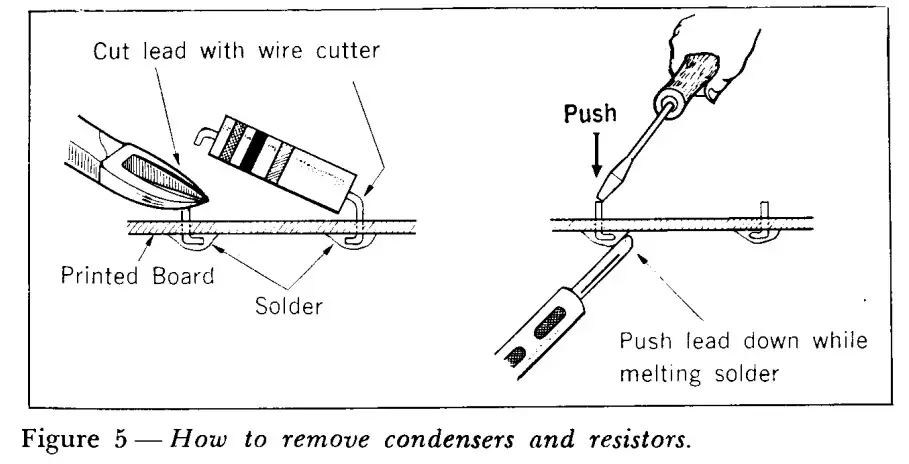
When it is found necessary to replace a condenser or resistor mounted on the printed board, care must be taken not to damage the circuit pattern. Never attempt to pull them out forcefully. Cut off the leads with a wire cutter as shown in Figure 5 to remove them.
REVISING A PART OF THE PRINTED PATTERN
When it is desired to revise part of a printed pattern, do so as follows:
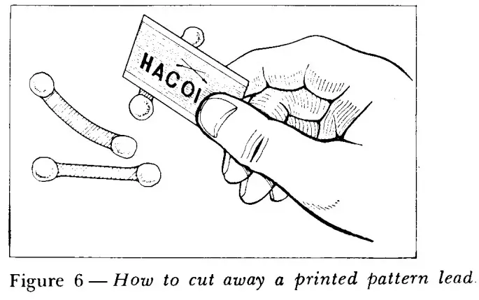
How to cut off a pattern path
Use a razor blade and pressing it down firmly, cut off the desired pattern path as shown in Figure 6. The path can be cut with one stroke. When it is desired to join two paths, solder a jumper lead across the paths.

WHEN THE RECEIVER FAILS TO OPERATE
When the receiver fails to operate, troubleshooting should be carried out starting from the audio stage and proceeding toward the front end.
AUDIO STAGE CHECK — A low hum should be heard when the end of the lead from the AF-VR terminal of the printed board is touched, indicating that the audio stage is working properly. If nothing is heard, check for defective tubes or an open output transformer.
IF STAGE CHECK — Feed a modulated 455 kHz signal to the V2 mixer tube. If the modulated signal is heard through the audio stage, it means that the IF stage and thereafter are working properly. Another way to check the IF stage is to touch the grid circuits with a screwdriver. A click response indicates it is working properly.
It should be noted that if the IF transformers are grossly misaligned, no response will be heard even if there happens to be no miswiring or defective parts.
Frequent trouble is the failure of the oscillator stage. Failure to oscillate may occur on all bands or on just one single band. In such a case locate the oscillator grid and the 22 K ohm resistor connected to it. Insert a millimeter in series with the lead from this 22 K ohm resistor to the chassis. No reading indicates the oscillator is not functioning. More than 0.1 milliamperes current flow indicates it is working properly.
If the above tests prove that all the circuits are working properly, look for trouble in the RF or antenna circuit. Remember that improper tracking alignment will result in considerable sensitivity loss, and this can often lead to a mistaken analysis that miswiring or a defective part is at fault.
MAINTENANCE
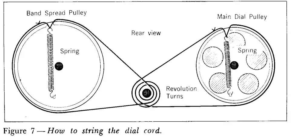
- REPLACING THE DIAL CORDWhen replacing a dial cord, string it according to the order shown in Figure 7. Always use a special radio dial cord for replacement purposes.
- FUSE REPLACEMENTA 1-ampere glass tube fuse should be used in replacing a blown fuse. The blown fuse can be removed by turning the fuse holder in a counterclockwise direction. Before replacing a fuse, always be sure to check for possible causes of failure and make repairs when necessary.
- PILOT LAMPUse a swan base type 8 volt pilot lamp for replacement purposes.
- REPLACEMENT OF RESISTORSReplacement of resistors can be made when necessary with one within plus or minus 10% in value of the original resistor. For example, a 330-ohm resistor can be replaced with one of 300 ohms, if necessary, without adversely affecting receiver performance.

FREQUENCY RANGES:
550 —1600 kHz1.6 — 4.8 MHz4.8— 14.5 MHz10.5 —30 MHz
BANDSPREAD:(Direct Reading on Ham Bands)
| 3.5 MHz | 80m |
| 7 MHz | 40m |
| 14 MHz | 20m |
| 21 MHz | 15m |
| 28 MHz | 10m |
| SENSITIVITY: A, B, C, BANDS — Less than 6 dB (for 10 dB S/N ratio)
D BAND — 13 MHz; Less than 18 dB (for 10 dB S/N ratio) 28 MHz; Less than 10 dB (for 10 dB S/N ratio) |
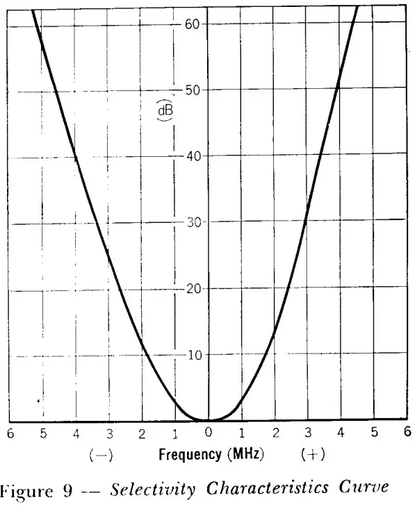
| SELECTIVITY: -±-5 kHz at —50 dBAUDIO POWER OUTPUT: 1.5 wattsPOWER SUPPLY: AC 110 —120 / 220 — 240 V, 50/60 Hz |
POWER CONSUMPTION: 45 wattsTUBES & DIODES USED:6BA6 RF Amplifier6BE6 Mixer6AQ8 Oscillator6BA6 I. F. Amplifier1N60 DetectorS-1.5-02 ANL5-1.5-02 1N60 AVC1/2 6AQ8 BE
| 1/2 6AQ8 | Audio Amplifier |
| 6AQ5 | Audio Power Output |
5-05-08 X 2 Rectifier
| 1N60 | For S Meter |
RECOMMENDED SPEAKER TYPE:4 or 8-ohm permanent magnet dynamic speaker (requires no output transformer)
DIMENSIONS:7″ H, 15″ W, 10″ D.
WEIGHT:18.8 lbs.
BUILT-IN CIRCUITS:BandspreadAutomatic Noise Limiter (ANL)Automatic Volume Control (AVC)Headphone Jack
SCHEMATIC DIAGRAM
 report this ad
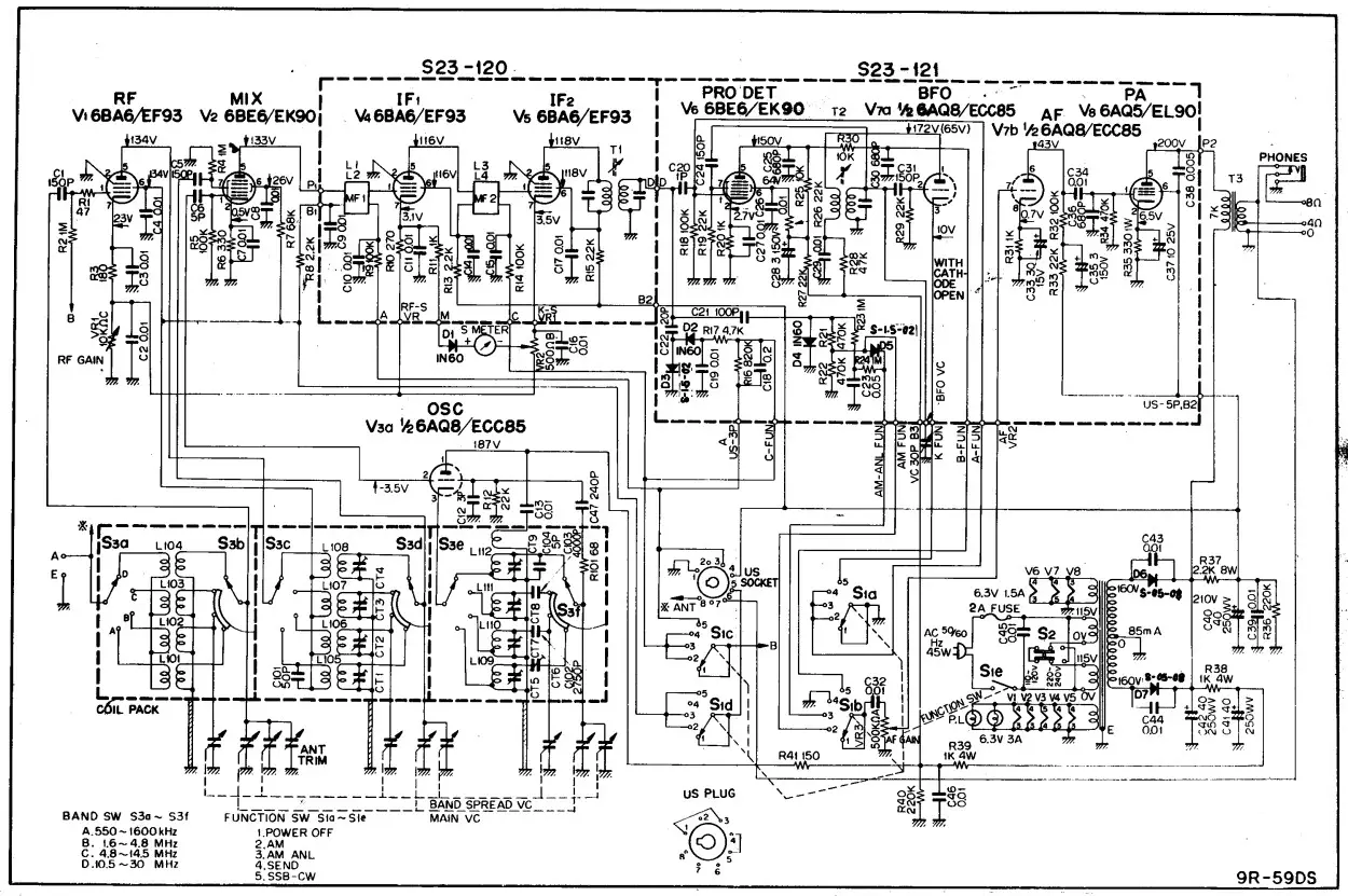
[xyz-ips snippet=”download-snippet”]