User ManualCBF200Circuit Breaker Finder
Introduction
Congratulations on your purchase of the Triplett CBF200 Circuit Breaker Finder. The Circuit Breaker Finder is a multi-function circuit tracer/ identifier. This device is formed by one (1) Transmitter and one (1) Receiver. There are 3 functions:
- Socket Tester (Wire Mapping)
- Circuit Tracing / Identifying
- Non-Contact Voltage Detecting.
The transmitter can check the wiring condition and GFCI function of the socket; it will also send the signal along the wire for the Receiver to identify the No Fuse Breaker (NFB). Based on the signal strength from the transmitter, the Receiver will help a user to identify the NFB. Before identifying the NFB, the user can use the Non-Contact Voltage Detection (NCV) function of the Receiver to check if the circuit is live.
Safety
International Safety Symbols
SAFETY NOTES
| Symbol | Description |
| Measurement Category II is applicable to test and measure circuits connected directly to utilization points (socket outlets and similar points) of the low-voltage MAINS installation. | |
| RISK OF DANGER, Measurement Category III is applicable to test and measure circuits connected to the direct part of the building’s low-voltage MAINS installation. | |
 |
WARNING. This symbol, adjacent to another symbol or terminal, indicates the user must refer to the manual for further information. CAUTION, RISK OF DANGER. |
 |
WARNING. This symbol, adjacent to a terminal, indicates that, under normal use, hazardous voltages may be present, CAUTION, Risk OF Electric Shock. |
|
PROTECTIVE CONDUCTOR TERMINAL |
| Direct Current | |
| Alternating Current | |
| Both direct and alternat | |
 |
Equipment protected throughout by DOUBLE INSULATION or REINFORCED INSULATION |
Description
Meter Description
(a) Sensor: For detecting the signal from the Transmitter and test tip for NCV mode.(b) Power Indication: LED will flash when battery power is low.(c) NFB/Comparison Mode Indication: The LED will stay bright during NFB Searching Mode, and the LED will flash during NFB Comparison Mode.(d) NCV Indication: LED will light up during NCV Mode.(e) Signal Strength Indication: The stronger the signal, the faster the LED flashing speed and buzzer voice.(f) NCV/NFB Switch Button: Short press to switch between NCV and NFB mode. Press and hold this button to enter NFB Comparison Mode during NFB Mode.
- Sensitivity Level Indication: Indicate current sensitivity level.
 /GAIN Button: Press and hold this button to switch on and off the Receiver. Short press this button to adjust the sensitivity.
- GFCI test button: Press this button to test the GFCI function.
- Wire Mapping Indication: Indicating the wiring condition.
Function of Transmitter
- Wire Mapping of Power ReceptacleTesting Method: Plug the transmitter into the receptacle and check the light indication with the below circumstances. If no LED lights up, it means no power or no live wire.
Receptacle Wire Mapping
LED1 LED2 LED3 Wiring Condition ON OFF ON CORRECT WIRING ON OFF OFF OPEN GROUND ON ON OFF REVERSE HOT & NEUTRAL OFF OFF OFF OPEN HOT OFF OFF ON OPEN NEUTRAL OFF ON ON REVERSE HOT & GROUND OFF ON OFF HOT ON NEUTRAL WITH HOT OPEN - By pressing the GFCI button on the transmitter for a few seconds can check if the ground fault interrupter / residual current device is functioning properly.Testing Method: Plug the Transmitter into the receptacle, press the GFCI button for a few seconds when it is correct wiring. The GFCI should cut off the power very quickly.
- By plugging the Transmitter into the receptacle, the transmitter is able to send signals into the wire for the Receiver to locate the No Fuse Breaker (NFB).
CAUTION:
- If “OPEN GROUND” and “HOT/NEUTRAL REVERSE” happen at the same time, the “OPEN GROUND” indication will appear in higher priority. Consequently, the user needs to fix the “OPEN GROUND” problem, and then check the wire mapping again to see if there is any other wrong wiring.
- The tester cannot detect GROUND and NEUTRAL REVERSE.
- Make sure all wires are connected correctly before the GFCI test, otherwise the GFCI test may be failed.
- Always check the wire mapping if the socket has been modified.
Function of Receiver
- Non-Contact Voltage Detection(NCV)This mode is able to detect the live power by sensing the electric field from the live power. There are 4 sensitivity levels for NCV Mode. The flashing speed will be faster and the buzzer voice will be louder as the Receiver approaches the voltage source.
- No Fuse Breaker (NFB) FinderThe Transmitter sends the signal along the wire, and the Receiver can detect the electromagnetic field from the signal. Based on this design, the user can locate the No Fuse Breaker and the connected receptacle quickly without switching off any NFB.
How to Connect

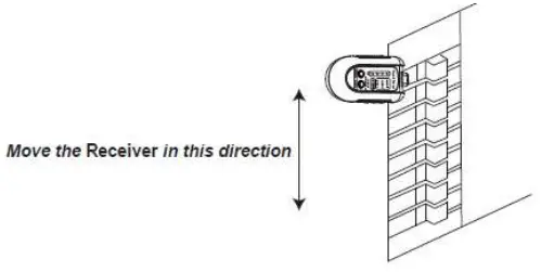
Direction of Receiver
To improve the accuracy during detection, please place the Receiver in the center of the NFB. The sensor is about the same size as single NFB width.
Operation of Receiver
Receiver: NFB Mode
For this mode, the Receiver will detect the signal sent from the Transmitter, and locate the No Fuse Breaker (Circuit Breaker).
There are two ways to locate the No Fuse Breaker:A. Searching ModeB. Comparison Mode.
NFB Searching Mode:
- Keep the Receiver away from the power source and press and hold the ” /GAIN BUTTON ” to switch on the power. The Receiver will start self-calibration with a “Bi” voice. The 4 LEDs of the sensitivity will flow during the calibration. The 4 LEDs of the sensitivity will stop the flow with the “Bi-Bi” voice twice when self-calibration is done, and NFB indication will light up. The Receiver is in NFB Search Mode now. There are 5 levels of sensitivity for NFB Search Mode. Sensitivity Indication 1 4 the higher the number, the higher the sensitivity. It is minus gain when no Sensitivity Indication lights up. This is for a very strong signal source. You can adjust the sensitivity by pressing the” /GAIN BUTTON “. The initial sensitivity of the Receiver is minus gain.
- Plug the Transmitter into the receptacle and check the wire mapping from the transmitter Wire Mapping If it is correctly wired, the user can start searching for the corresponding No Fuse Breaker from the distribution panel.
- Approach the Receiver with the No Fuse Breaker to start the search. The sensor of the Receiver must be in the same direction as the current of the No Fuse Breaker to achieve the best sensitivity. The signal strength detected by the Receiver will be shown by the SIGNAL INDICATION LED and the BUZZER VOICE. The flashing speed will increase as the signal gets stronger. The buzzer will also tweet faster as the signal gets stronger. If multiple breakers show long bright LED and long tweeting, the user may need to decrease the sensitivity. In contrast, if no significant LED indication and tweeting voice, increase the sensitivity.
- During the breaker search, move the Receiver one by one along with the No Fuse Breakers. Make sure the sensor stays in the center of each breaker and stays on each breaker for a few seconds to obtain a stable signal indication. The suggested direction between Receiver and No Fuse Breaker is illustrated below (the Receiver is in the same direction as the switch of the breaker).
(5) Due to the connection in the distribution panel, sometimes it will be difficult to judge the strongest No Fuse Breaker from the LED indication and buzzer voice because they are branch breakers from one of the main breakers. This generally happens when the user has scanned all circuit breakers, and there are still 2 to 3 circuit breakers left with similar signal strength. If this happens, try NFB Comparison Mode with these 2 3 circuit breakers.
NFB COMPARISON MODE:
This mode can help the user determine the strongest signal when there are multiple No Fuse Breakers with similar signal strengths by reading the LED flashing speed and buzzer voice. In this mode, the user must select one of the No Fuse Breakers as the criterion for comparison, then move the Receiver to the other No Fuse Breaker. The Receiver will compare the other No Fuse Breaker with the criterion, and only if the signal strength on the other No Fuse Breaker is stronger than the criterion will activate the signal indicate on LED to light up, and the buzzer will tweet. By repeating the comparison, the user can reject the incorrect No Fuse Breaker.
To start comparison mode, please follow the below procedure:
- Put the Receiver on top of a No Fuse Breaker, which the user is going to set as the criterion.
- Press and hold the “NCV/NFB” Button when the Receiver is under NFB Searching Mode. The Receiver will memorize the signal strength of the criterion, and the NFB Indicate on LED will start flashing after entering NFB Comparison
- The Sensitivity Level of the NFB Comparison Mode will be the same as the NFB Searching Mode. For example, if using Sensitivity Level 3 for NFB Searching Mode. It will be Sensitivity Level 3 for the NFB Comparison Mode. You need to return to NFB Searching Mode if you want to change the Sensitivity Level. This is to make sure you are comparing different NFBs with the same sensitivity.
- Move the Receiver on top of the other No Fuse Breaker. If the signal strength of other No Fuse Breakers is stronger than the criterion, the Signal Indication will light up, and the buzzer will tweet.
- To exit the NFB Comparison Mode, press the “NCV/NFB”
Button or ” (
/GAIN” Button once shortly; the device will return to NFB Searching Mode.
For example, there are 3 No Fuse Breakers A, B, and C with similar signal strength. The user can put the Receiver on top of Breaker A, and set it as the criterion, then put the Receiver on top of Breaker B and C. If the LED and buzzer are not activated, Breaker A will be the correct No Fuse Breaker. If both B and C activate the LED and buzzer of the Receiver, it means either B or C is the correct No Fuse Breaker. Users can repeat the comparison mode procedure on Breaker B and C to find the correct No Fuse Breaker.
Receiver: NCV Mode
The Receiver will work as a Non-Contact Voltage Detector in this mode. This mode does not need to work with the Transmitter and can detect AC voltage > 24 V.
To start NCV Mode, follow the procedure below:
- Switch on the power and wait for the self-calibration.
- Press the “NFB/NCV” Button shortly to switch the function from NFB to NCV. The NCV Indication LED and the Level 1 Gain LED will light up.
- There are 4 levels of sensitivity; the user can adjust it by pressing 44 (5 /GAIN” Button shortly. The lower the number, the lower the sensitivity. Lower sensitivity is for high voltage detection, and higher sensitivity is for low voltage detection.The sensitivity level and suggested voltage detection level are as below:Sensitivity Level 1: Suggested for voltage > 180 VACSensitivity Level 2: Suggested for voltage > 90 VACSensitivity Level 3: Suggested for voltage >60 VACSensitivity Level 4: Suggested for voltage >24 VACThe value is for reference only.
- The user can detect the AC voltage now; the closer to the power source, the faster the SIGNAL Indicator LED flashing and buzzer tweeting. You can decrease the sensitivity if the NCV indication is saturated (The indication from the LED and Buzzer run without stopping).
Tip:
Sometimes the Live and Neutral terminals have very close signal strength, and it’s hard for users to define which is which. Users can rotate the detector sensor angle 90° to check if it obtains more clear indication.
CAUTION:
- The user is only able to enter/ exit NFB Comparison Mode under NFB Searching Mode.
- Make sure the Receiver is over the center of the No ruse Breaker when searching/comparing the signal.
- Wait a few seconds over of each No Fuse Breaker to obtain stable signal strength when the Receiver is in Searching/ Comparison Mode.
- Wait a few seconds over the No Fuse Breaker before selecting it as the criterion.
- Keep the Receiver away from the voltage source during self-calibration, or it may degrade the performance. If it is necessary, restart the Receiver to perform the self-calibration
- Make sure the Receiver is in the same direction as the current flow.If it is on the circuit breaker, try the same direction as the If it is on the wire, rotate the Receiver 90 degrees, so that the long side of the sensor is parallel with the wire.
- While tracing the NFB signal from the wires, the signal may be too strong to recognize the difference due to the distance and wiring condition between the Receiver and Transmitter, try a different Gain Level.
- The sensitivity level and suggested voltage detection level are as below:
Sensitivity Level 1: Suggested for voltage > 180 VACSensitivity Level 2: Suggested for voltage > 90 VACSensitivity Level 3: Suggested for voltage >60 VACSensitivity Level 4: Suggested for voltage >24 VAC
This value is for reference only. The actual performance may vary depending on the installation of the voltage source.
- The NCV indication may be saturated with any level of sensitivity if the user measures the conductor directly.
BATTERY REPLACEMENT
The Receiver will automatically shut down after 10 minutes without any operation. The Low Power LED will flash slowly when battery power is low; for good detecting performance, replace the battery. If battery power is too low for the device to stay activated, the Low Power LED will flash rapidly and shut down the power automatically after 20 seconds. To replace the battery, please see the illustration below.
MAINTENANCE
- Keep away from water and dust.
- Do not operate and store the meter in high temperature, high moisture, flammable, explosive, and strong magnetic
- Do not use abrasives, alcohol, or solvents to clean the meter.
- Take off the battery if storing the tester for a long period.
Specifications
Circuit Breaker Finder— ReceiverBattery: 9V Alkaline x 1Auto Shut Down: After 10 minutes without any operationNon-Contact Voltage Detect on: 24–300VAC
Circuit Breaker Finder—TransmitterVoltage: 120VAC Single Phase Two Wires (Live, Neutral) with GroundFrequency: 47 — 63 HzGFCI Leaking Current: 7mA @ 120VAC
 report this ad
GeneralOperating Environment: 0–50°C(32″122°F); 3080% RH max; 50% RH above 30°CStorage Environment: -3070°C(-22158°F); 80% RH maxDimensions: Transmitter 4.7 x 2.5 x 1.3″ (118.5 x 63 x 32mm)Receiver 5.1 x 2.4 x 1.5″ (130 x 62 x 36.9mm) Weight: 9.8oz (260g)Altitude: < 2000m, for indoor application onlyPollution Degree: 2Safety Standard:UL 61010-1UL 61010-2-030CAT II 300V (Transmitter)CAT III 300V (Receiver)
Warranty Information
Triplett / Jewell Instruments extends the following warranty to the original purchaser of these goods for use. Triplett warrants to the original purchaser for use that the products sold by it will be free from defects in workmanship and material for a period of (1) one year from the date of purchase. This warranty does not apply to any of our products that have been repaired or altered by unauthorized persons in any way or purchased from unauthorized distributors so as, in our sole judgment, to injure their stability or reliability, or which have been subject to misuse, abuse, misapplication, negligence, accident or which have had the serial numbers altered, defaced, or removed. Accessories, including batteries, are not covered by this warranty
Copyright © 2020 Triplettwww.triplett.com
[xyz-ips snippet=”download-snippet”]