![]() IRT350Circular Laser IR ThermometerUSER MANUAL
IRT350Circular Laser IR ThermometerUSER MANUAL
Introduction
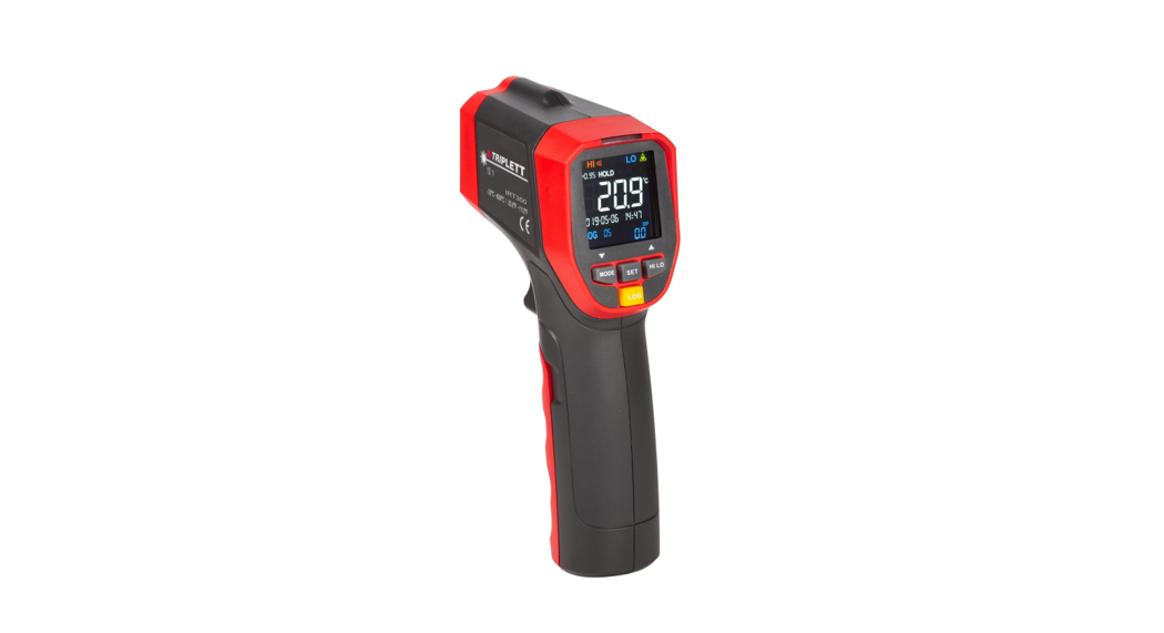
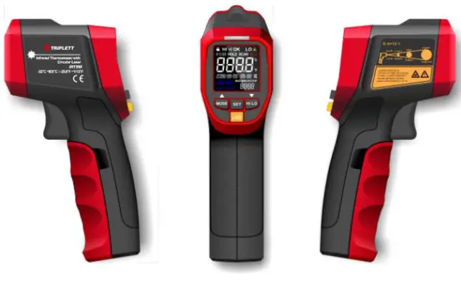
Congratulations on your purchase of the Triplett IRT350 12:1 Circular Laser Infrared Thermometer. This thermometer can quickly and accurately determine the surface temperature by measuring the infrared energy radiated from the target surface. The circular laser accurately indicates the target and the area within it.
Safety
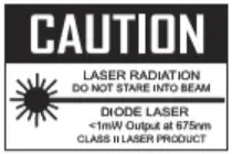
![]() Warnings:To prevent eye damage or personal injury, please read the following safety instructions before using the thermometer:Please do not irradiate people or animals with laser directly or indirectly.
Warnings:To prevent eye damage or personal injury, please read the following safety instructions before using the thermometer:Please do not irradiate people or animals with laser directly or indirectly.
 Precautions:
Do not look directly at the laser emitter.Do not disassemble or modify the thermometer or laser.To ensure the safety and accuracy of the thermometer, it should only be repaired by a qualified professional using the original replacement parts.If the battery symbol on the LCD display is flashing, please replace the battery immediately to prevent inaccurate measurement.Inspect the case before using the thermometer. Do not use the thermometer if it appears damaged. Look for cracks or missing plastic.Please refer to the emissivity information for the actual temperature.Highly reflective objects or transparent materials can cause the measured temperature value to be lower than the actual temperature.When measuCircular high-temperature surfaces, please be aware not to touch them.Do not use the thermometer in an environment close to flammable or explosive substances.Using the thermometer around steam, dust, or environments with large temperature fluctuations may lead to inaccurate temperature measurement.To ensure measurement accuracy, please place the thermometer in the measurement environment for 30 minutes before using it.Avoid keeping the thermometer near a high-temperature environment for long period.
Specifications
| D:S ratio | 12:01 |
| MeasuCircular range | -20°C-600°C/ -4.0°F-1112°F |
| LCD size | 1.2x 1.2″ (30mm*30mm) |
| LCD display | Color EBTN (Enhanced Black TwistedNematic) |
| Accuracy | <0°C: ± (1.5°C+0.1°C/°C);>_0°C: ±1.5°C or ±1.5% of reading,whichever is greater<32°F: ± (3.0°F+0.1°F/°F);32°F: ±3.0°F or ±1.5% of reading,whichever is greater |
| Temperature coefficient | ±0.1°C/°C or ±0.1%/°C, whichever isgreater(±0.1°F/°F or ±0.1%/°F, whichever isgreater) |
| Repeatability | 0.7°C or 0.7%, whichever is greater(1.5°F or 0.7%, whichever is greater) |
| Emissivity | 0.11.0 (adjustable, can store 5 sets ofpreset values) |
| Response time | 5.250ms (95% of reading) |
| Spectral response | 8um-14um |
| Auto power off | 15s |
| Low battery indication | √ |
| High/Low temperature Audible and LED alarms | √ |
| Data hold | √ |
| Unitconversion (°C/°F) | √ |
| MAX/MIN/AV G/DIF mode | √ |
| Lock measurement | √ |
| Data storage | 99 sets |
| Scheduled measurement | The interval from 1 minute to 4 days; up to 99times |
| Laser | Circular laser, wavelength 630nm-670nm,output power <1mW, class 2 laser |
| Operating temperature | 0°C-50°C (32°F-122°F) |
| Storage temperature | -20°C-60°C (-4°F-140°F) |
| Operating humidity | <90%RH (non-condensing) |
| Drop test | 1m |
| Battery type | 9V alkaline battery (1604A) |
| Battery life | ≥8 hours (continuous temperature measurement) |
| Product netweight | 7.2oz (204g)6.3”x 3.5” X1.9”(161.5mm×90mm ×48mm) |
| Product size |
**NOTE: In some places with strong electromagnetic interference, the product measurement result may change by up to ±10°C or 20% of the measured value (taking whichever is greater). Safety StandardsCE certification: EN61326-1:2013Laser safety standard: EN60825-1:2014
Reference StandardJJG 856-2015
Features
- Circular laser indication, which can indicate the target area under test more accurately and intuitively
- Bright color EBTN display
- MAX/MIN/AVG/DIF value reading
- 5 sets of high/low-temperature alarm preset values and 5 sets of emissivity preset values can be stored for users to set up quickly.
- With tri-color (red, green, and blue) LED and buzzer alarm functions
- Lock measurement, for processes that require temperature monitor circular
- 99 sets of data logging with date and time
- Scheduled measurement, for occasions where timing temperaturemonitoCircular is required
- Tripod mount
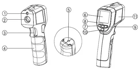
External Structure
| 1 | Laser |
| 2 | Infrared sensor |
| 3 | Trigger |
| 4 | Battery coverTripod mounting hole |
| 6 | LCD |
| 7 | MODE button |
| 8 | SET button |
| 9 | 1-11/L0 button |
| 10 | LOG button |
| 11 | Laser warning label |
Display Description
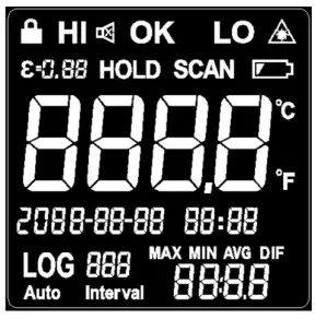
 |
Lock measurement indicator | HI OK LO | Temperature measurement alarm indicator |
 |
Buzzer indicator | Laser indicator | |
| HOLD | Temperature hold indicator | SCAN | Temperature measurement indicator |
| Low battery indicator | °C°F | Temperature unit indicator |
| Emissivityindication | The main display of the measured temperature | ||
| MAX-MIN AVG DIF | Measurement mode indication | Auxiliary display of the measured temperature | |
| Temperature logging mode and group number | AutoInterval | Scheduled measurement mark | |
| Date and time |
Operating Instructions
Viewing the Last Measured ValueIn the off state, short press (less than 0.5s) the trigger to turn on the thermometer and the measurement data held before last shutdown will be displayed. Toggle to view the MAX/MIN/AVG/DIF value by short pressing the MODE button.
Auto Power OffIn the HOLD mode, if there is no operation for 15s, the thermometer will automatically power off and store the currently held measurement.
Manual Measurement
- Pull and hold the trigger after aiming at the target. The SCAN icon will flash indicating that the target object’s temperature is being measured. The measurement result will be updated on the LCD.
- Release the trigger, the SCAN icon disappears, and the HOLD icon appears, indicating that the measurement has been stopped and the last measured value is held.
Lock Measurement
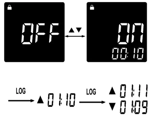
- In the HOLD interface, press the SET button for 3s to enter the lock measurement setting interface, and turn on/off the lock measurement by pressing the or button. When the lock measurement is turned on, short press the LOG button to perform the time setting “00:00” for the lock measurement. At this time, the selected time position flashes, and the time value can be adjusted by pressing the or button. Set the time to “00:00” to turn off the timing function.
- When the lock measurement is turned on, short press the trigger to enable it. The icon will appear on the thermometer screen and the SCAN icon will flash. The thermometer will continuously measure the target temperature.
- Pull the trigger again, the and SCAN icons disappear, and the HOLD icon appears. The thermometer stops the measurement and holds the last measured value.
- After setting the lock measurement time (1 minute to 5 hours), the measurement starts after the activation of the lock function. When the set time is reached, the thermometer will automatically power off and store the last measured value. Short press (less than 0.5s) is the trigger to turn on the thermometer to view the measured value (NOTE: The measured value will be cleared by the long press).
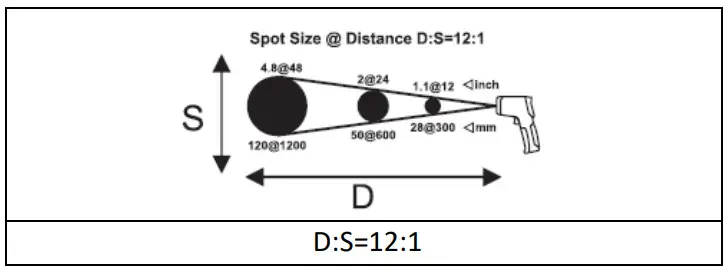
NOTE: During measurement, it is best to ensure that the measured target diameter is twice the spot size (S) of the thermometer, and then determine the test distance (D) according to the D:S diagram For example, if you use the IRT350 to measure the temperature of an object with a diameter of about 4’’ (10cm), then according to the above, the spot size (S) of the thermometer should be about 2’’ (5cm) for highest accuracy, and according to the D:S diagram, the measured distance (D) is about 24’’ (60 cm).
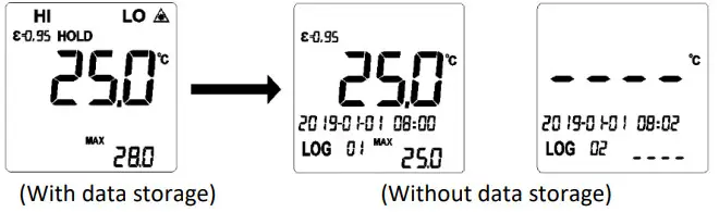
Measurement Mode with Data Storage Function
- Enter the measurement mode with data storage function:In the HOLD interface, short press the LOG button to enter the measurement mode with the data storage function. The screen will display the LOG icon and the log group number.
- Store data:In the measurement mode with data storage function, first select the storage location from “01-99” by pressing the or button. If the selected location has stored data, the temperature value and storage time will be displayed; if there is no data, “—-” will be displayed. After selecting the location, pull the trigger for measurement. After completing the measurement, short press the LOG button. The screen will flash three times to indicate the success of the data storage and automatically switch to the next location.
- Query storage data:In the measurement mode with the data storage function, press the or button to query the storage data and storage time corresponding to the location. If there is no data, “—-” will be displayed.
- Delete all storage data:In the measurement mode with data storage function, long-press the LOG button until the log group number is switched to “01” after 10s flashing of the screen.
- Exit the measurement mode with data storage function:In the measurement mode with data storage function, press the LOG button for 3s until the screen starts to flash to exit.
Scheduled Measurement
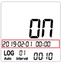
- In the HOLD interface, press the SET button for 3s to enter the lock measurement setting interface, then short press the SET button once to enter the scheduled measurement setting interface, and turn on/off the scheduled measurement by pressing the or button.
- After turning on the scheduled measurement, follow the steps below to set its parameters:a) Short press the LOG button to select “Year → Month → Day → Hour → Minute” in turn to set the start time of the scheduled measurement. At this time, the selected setting position flashes, and the value can be adjusted by pressing the or button. NOTE:The start time cannot be set less than the current system time, otherwise, the scheduled measurement will not be executed.b) After setting the start time, short press the LOG button to select “Hour → Minute” in turn to set the interval time of the scheduled measurement.c) After setting the interval time, short press the LOG button to set times (01-99) of the scheduled measurement in turn.d) After setting the parameters, press the SET button or pull the trigger to return to the HOLD interface. The Auto Interval icon will flash. When the start time of the scheduled measurement is reached, the thermometer will automatically start temperature measurement and store the current time and measured value. Each time the interval time is reached, the thermometer will automatically measure and store the current data, until the last interval.
- In the HOLD interface, press the LOG button for 3s to enter the scheduled measurement log value query mode. The screen will display the Auto Interval icon, the LOG icon and the log group number. In this mode, press the or button to query the measured temperature value corresponding to the scheduled time, press the LOG button for 10s to delete all storage values of the scheduled measurement, and short press the LOG button or pull the trigger to exit.

 b) After setting the start time, short press the LOG button to select “Hour → Minute” in turn to set the interval time of the scheduled measurement.
 c) After setting the interval time, short press the LOG button to set times (01-99) of the scheduled measurement in turn.
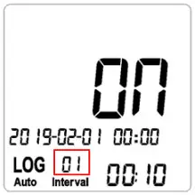 d) After setting the parameters, press the SET button or pull the trigger to return to the HOLD interface. The Auto Interval icon will flash. When the start time of the scheduled measurement is reached, the thermometer will automatically start temperature measurement and store the current time and measured value. Each time the interval time is reached, the thermometer will automatically measure and store the current data, until the last interval.
System Time Setting
In the HOLD interface, press the SET button for 3s to enter the lock measurement setting interface, and short press the SET button twice to enter the system time setting interface. Short press the LOG button to select “Year→ Month → Day → Hour→ Minute” in turn and set the corresponding parameters. At this time, the selected setting position flashes, and the value can be adjusted by pressing the or button. Add or subtract 1 each time by short press, and add or subtract 10 per second by long press. Short press the SET button or pull the trigger to exit the system time setting.NOTE: System time needs to be reset after battery replacement or power failure.
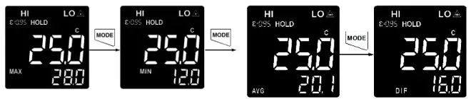
MAX/MIN/AVG/DIF Value ReadingShort press the MODE button to switch the “MAX → MIN → AVG → DIF” measurement mode in turn and the temperature value of the corresponding mode will be shown in the auxiliary display area (as shown below).
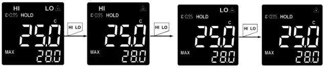
High/Low-Temperature Alarm On/OffShort press the HI/LO button to turn the high/low limit alarm function on and off in sequence.
When HI limit alarm function is turned on and the measured temperature value is higher than the set high alarm limit, the red LED and HI indicator flash. If the audible alarm function has been turned on, the buzzer will beep.
When the LO limit alarm function is turned on and the measured temperature value is lower than the set low alarm limit, the blue LED and LO indicator flash. If the audible alarm function has been turned on, the buzzer will beep.
When HI/LO limit alarm function is turned on and the measured temperature value is within the high and low alarm limit range, the green LED lights up and the OK indicator is displayed, indicating that the measured temperature is normal.
Function Setting
In setting mode, pull the trigger, short press the SET button continuously or wait for 10s to exit.
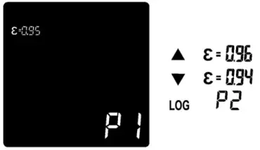
- High/Low Alarm Limit SettingIn the HOLD interface, short press the SET button once/twice to enter the high/low alarm limit setting interface. Short press the LOG button to quickly select the preset high/low alarm limit value (P1-P5). If there is no desired value among the preset values, select any value closest to the high/low alarm limit, and adjust it by pressing the or button. Add or subtract 1 each time by short press, and add or subtract 10 per second by long press.
- Emissivity SettingIn the HOLD interface, short press the SET button until the emissivity setting interface is displayed. Short press the LOG button to quickly select the or button. Add or subtract 0.01 each time by short press, and add or subtract 0.1 per second by long press.
- Temperature Unit SettingIn the HOLD interface, short press the SET button until the temperature unit setting interface is displayed, and switch between °C and °F by pressing the or button.
- Audible Alarm SettingIn the HOLD interface, short press the SET button until the audible alarm setting interface is displayed, and turn on/off the audible alarm by pressing the or button.
- Laser Indication Function SettingIn the HOLD interface, short press the SET button until the laser indication function setting interface is displayed, and turn on/off the laser indication function by pressing the or button. When it is turned on, the laser indicator will be displayed on the LCD, and the laser will accurately indicate the position you are measuring the temperature measurement.

NOTE: Please follow the laser precautions when the laser is turned on to avoid damage to human or animal eyes.
D:S (Distance and Spot Size)As the distance (D) from the target being measured to the thermometer increases, the spot size (S) on the measured area becomes larger. The relationship between the distance and the spot size is as shown below.
Field of View
Make sure that the measured target is larger than the spot size. The smaller the target, the closer the test distance should be (please refer to D:S for the spot size at different distances). To obtain the optimum measurement result, it is recommended that the target being measured is 2 times larger than the spot size.
Emissivity
Emissivity is a symbol of the energy radiation of a material. The emissivity of most organic materials and coated or oxidized surfaces is about 0.95. To measure the temperature of a bright metal surface, cover the surface to be tested with masking tape or matt black paint with a high emissivity setting (if it is possible), wait for a period of time, and measure the temperature of the tape or black paint surface when it reaches the same temperature on the surface of the object covered below. The total emissivity of some metals and non-metals are listed in the following table.
| Measured Surfaces | Emissivity |
| Metal | |
| AluminumOxidization | 0.2-0.4 |
| A3003 AlloyOxidizationRough | 0.30.1-0.3 |
| BrassBurnishingOxidization | 0.30.5 |
| CopperOxidizationElectric TerminalBoard | 0.4-0.80.6 |
| HastelloyAlloy | 0.3-0.8 |
| InconelOxidizationSand-BlastingElectro Burnishing | 0.7-0.950.3-0.60.15 |
| IronOxidization | 0.5-0.9 |
| Rusting | 0.5-0.7 |
| Iron (Casting)OxidizationNon-OxidizationCasting | 0.6-0.950.20.2-0.3 |
| Iron (Forging)Passivation | 0.9 |
| LeadRoughOxidization | 0.40.2-0.6 |
| MolybdenumOxidization | 0.2-0.6 |
| NickelOxidization | 0.2-0.5 |
| PlatinumBlack | 0.9 |
| BlackSteelCold RollingSteel Plate RubbingSteel Plate Burnishing | 0.7-0.90.4-0.60.1 |
| ZincOxidization | 0.1 |
| Non-Metal | |
| Asbestos | 0.95 |
| AsphaltBasalt | 0.950.7 |
| CarbonNon-OxidizationGraphiteSilicon Carbide | 0.8-0.90.7-0.80.9 |
| Ceramics | 0.95 |
| Clay | 0.95 |
| Concrete | 0.95 |
| Cloth | 0.9 |
| GlassConvex GlassSmooth GlassLead-Boron Glass | 0.76-0.80.92-0.940.78-0.82 |
| Plates | 0.96 |
| Plaster | 0.8-0.95 |
| Ice | 0.98 |
| Limestone | 0.98 |
| Paper | 0.95 |
| Plastics | 0.95 |
| Water | 0.93 |
| Soil | 0.9-0.98 |
| Wood | 0.9-0.95 |
Maintenance
CleaningUse clean compressed air to blow away falling particles.Use a wet cotton swab to carefully wipe the lens surface.Use a wet sponge or soft cloth to clean the product exterior.Do not rinse the thermometer or immerse it in water.
Battery Replacement
Install or replace a 9V alkaline battery (1604A) as follows:
- Open the battery cover.
- Insert the battery and pay attention to the polarity.
- Close the battery cover.
Warranty Information
Triplett / Jewell Instruments extends the following warranty to the original purchaser of these goods for use. Triplett warrants to the original purchaser for use that the products sold by it will be free from defects in workmanship and material for a period of (1) one year from the date of purchase.This warranty does not apply to any of our products that have been repaired or altered by unauthorized persons in any way or purchased from unauthorized distributors so as, in our sole judgment, to injure their stability or reliability, or which have been subject to misuse, abuse, misapplication, negligence, accident or which have had the serial numbers altered, defaced, or removed. Accessories, including batteries, are not covered by this warranty.
Copyright © 2019 Triplett
[xyz-ips snippet=”download-snippet”]