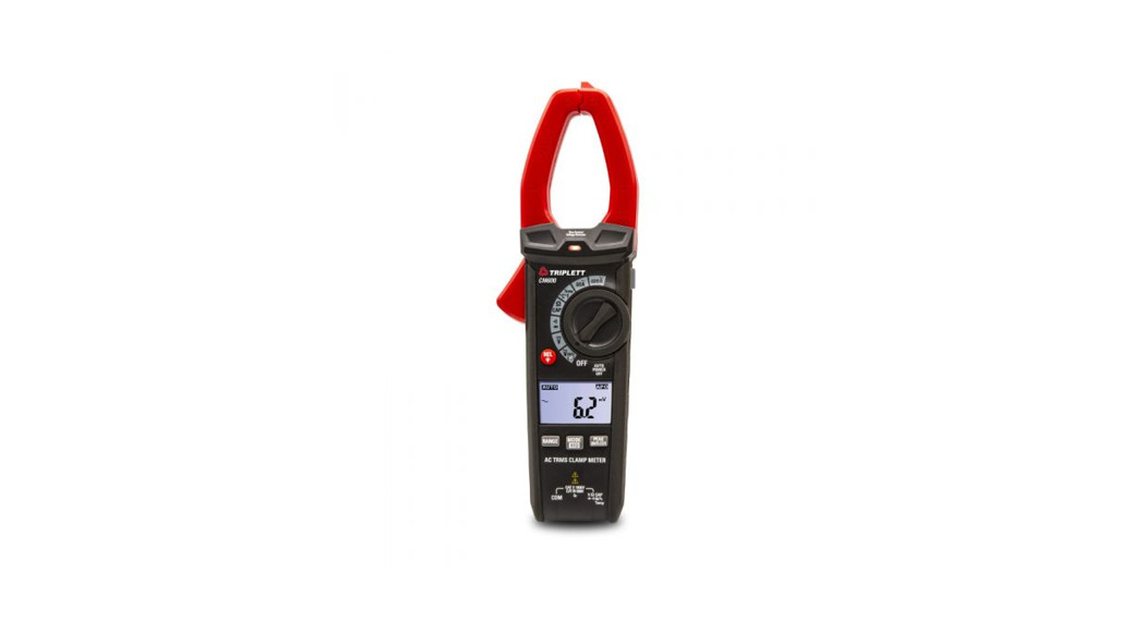
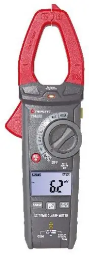
![]() User ManualCM600600A TRMS AC Clamp Meter
User ManualCM600600A TRMS AC Clamp Meter
Commonwealth Ave Woburn, MA 01801 Phone 781-665-1400 Toll-Free 1-800-517-8431![]() Visit us at www.TestEquipmentDepot.com
Visit us at www.TestEquipmentDepot.com
Introduction
Congratulations on your purchase of the Triplett CM600 600A True RMS AC Clamp meter. The CM600 True RMS AC Clamp meter features:
- AC Current measurements up to 600A.
- Variable Frequency Drive (VFD) Voltage Measurements
- Inrush Current Mode
- Temperature Measurements
- Non-contact AC voltage detection
- Auto Power OFF
Safety
International Safety Symbols
![]() This symbol, adjacent to another symbol or terminal, indicates the user must refer to the manual for further information.
This symbol, adjacent to another symbol or terminal, indicates the user must refer to the manual for further information.![]() This symbol, adjacent to a terminal, indicates that, under normal use, hazardous voltages may be present
This symbol, adjacent to a terminal, indicates that, under normal use, hazardous voltages may be present![]() Double insulation
Double insulation
SAFETY NOTES
- Do not exceed the maximum allowable input range of any function.
- When the instrument is not in use, press the ON/OFF key to turn off the
- Remove the battery if the meter is to be stored for longer than 60 days.
CAUTIONS
- Improper use of this meter can cause damage, shock, injury, or death.Read and understand this user manual before operating the meter.
- Always remove the test leads before replacing the battery.
- The meter itself for any damage before operating the meter. Repair or replace any damaged before use.
- Use great care when making measurements if the voltages are greater than 25VAC rms or 35VDC. These voltages are considered shock hazards.
- Voltage checks on electrical outlets can be difficult and misleading because of the uncertainty of connection to the recessed electrical Other means should be used to ensure that the terminals are not “live”.

Description
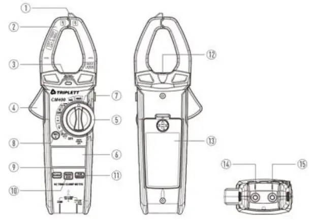
Meter Description
- NCV (Non-Contact Voltage) Sensor
- Current Clamp
- NCV (Non-Contact Voltage) Indicator LED
- Clamp Trigger
- Rotary Function Switch
- LCD Display
- Data HOLD/Flashlight Button
- REUBacklight Button
- Range Button
- MODE and VFD Button
- PEAK and INRUSH Button
- Flashlight
- Battery Cover
- COM Input Jack (-)
- Positive Input Jack (+)
Display Icons Description
| 1. REU ZERO Button2. Alternating Current/Voltage3. Direct Current Voltage4. Minus Sign5. Low Battery6. Auto Range Mode7. INRUSH Current Mode8. Display Hold9. MAX/MIN Mode | 10. Variable Frequency Drive (VFD) Voltage Value11. Diode Test12. Continuity Test13. Auto Power Off (APO)14. Faranheit and Celcius Units (Temperature)15. Units of Measure Prefixes16. Hertz (Frequency)17. Percent (%) Duty Cycle18. Measurement Display Digits |
Operation
AC Current Measurements
*NOTE: Ensure that the test leads are disconnected from the meter before making current clamp measurements. *
- Set the Function switch to the 600A If the approximate range of the measurement is not known, select the highest range then move to lower ranges if necessary.
- Press the REL button to zero the meter display.
- Use rotary function switch to select 60A AC or 600A AC range.
- Select AC current Test, press the INRUSH/PEAK Button to turn Inrush current test, the LCD will display “—“.
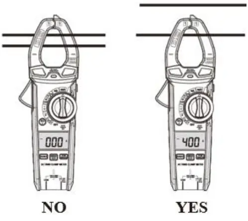
- Press the trigger to open the jaw, Fully, enclose only one conductor, For optimum results, center the conductor in the jaw.
- The clamp meter LCD will display the reading.
AC Voltage Measurements
- Insert the black test lead into the COM input jack and the red test lead into the Positive input jacks.
- Set the function switch to the VAC
- Press the MODENFD Button for 1 second to turn on the VFD test.
- Press the INRUSH/PEAK Button to turn on the PEAK test.
- Connect the test leads in parallel to the circuit under test.
- Read the voltage measurement on the LCD display.
DC Voltage Measurements
- Insert the black test lead into the COM input jack and the red test lead into the Positive input jacks.
- Set the function switch to the VDC
- Connect the test leads in parallel to the circuit under test.
- Read the voltage measurement on the LCD display. Resistance Measurements
- Insert the black test lead into the COM input jack and the red test lead into the Positive input jacks.
- Set the function switch to the OCAP position.
- Touch the test probe tips across the circuit or component under test.
- Read the resistance on the LCD display.
Continuity Measurements
- Insert the black test lead into the COM input jack and the red test lead into the Positive input jacks.
- Set the function switch to the “
 position.
 - Use the MODE Button to select continuity ” “, The display icons will change when the MODE button is pressed.
- Touch the test probe tips across the circuit or component under test.
- If the resistance is <500, a tone will sound.
Capacitance Measurements
WARNING: To avoid electric shock, discharge the capacitor under test before measuring.
- Set the function switch to the °CAP position.
- Insert the black test lead into the COM input jack and the red test lead into the Positive input jacks.
- Touch the test probe tips across the part under test, If “OL” appears in the display, remove and discharge the component.Read the capacitance value in the display.
- The display will indicate the proper decimal point and value.
Frequency Measurements
- Insert the black test lead into the COM input jack and the red test lead into the Positive input jacks.
- Set the function switch to the VAC Hz % position.
- Press the MODE button to select the Frequency (Hz) or Duty Cycle (%).
- Touch the test probe tips across the part under test.
- Read the value on the display.
- The display will indicate the proper decimal point and value.
Temperature Measurements
- Set the function switch to the TEMP position.
- Insert the Temperature Probe into the negative COM and Positive jacks, observing polarity.
- Touch the Temperature Probe head to the device under test, Continue to touch the part under test with the probe until the reading stabilizes.
- Read the temperature on the display, The digital reading will indicate the proper decimal point and value.
- Use the MODE Button to select °C or °F.
WARNING: To avoid electric shock, be sure the thermocouple probe has been removed before changing to another measurement function.
Diode Measurements
- Insert the black test lead into the COM input jack and the red test lead into the Positive input jacks.
- Turn the function switch to the “ “position.
- Use the MODE button to select the diode function if necessary (Diode symbol will appear on the LCD when in Diode test mode)
- Touch the test probe tips to the diode or semiconductor junction under Note the meter reading.
- Reverse the test lead polarity by reversing the red and black leads, Note this reading.
- The diode or junction can be evaluated as follows:
- If one reading displays a value (Typically 0.400V to 0.900V) and the other reading displays “OL”, the diode is good.
- If both readings display “OL” the device is open.
- If both readings are very small or ‘0’, the device is shorted.
Non-Contact Voltage (NCV) Measurements
WARNING: Risk of Electrocution, always test the Voltage Detector on a known live circuit to verify proper operation before use.
- Touch the probe tip to the hot conductor or insert it into the hot side of the electrical outlet.
- If AC voltage is present, the detector light will illuminate.
Note: The conductors in electrical cord sets are often twisted. For best results, rub the probe tip along a length of the cord to assure placing the tip in close proximity to the live conductor.Note: The detector is designed with high sensitivity. Static electricity or other sources of energy may randomly trip the sensor. This is a normal operation.
MODE and VFD Button
- Short Press the MODENFD Button to toggle between modes available for the rotary switch position (V/Hz/e/o)
- Long Press and Hold the MODENFD while POWERING ON will disable the Auto Power OFF (APO) Function
- Long Press and hold MODENFD will engage VFD measuring mode.
HOLD and Flashlight Button
- To freeze the LCD reading, press the Hold/Flashlight
- While the data hold is active, the “H” icon appears on the LCD.
- Press the Hold/Flashlight Button again to return to normal operation.
- The LCD is equipped with backlighting for easier viewing, especially in dimly lit
- Press the Hold/Flashlight Button to tum the Flashlight on, Press again to turn the Flashlight off.
Range Button
- Press the RANGE Button to activate the manual mode and to disable the Auto range function, The symbol “AUTO” disappears from the upper left part of the display.
- In manual mode, press the RANGE Button to change the measuring range, the relevant decimal point will change its position.
- The RANGE Button is not active in positions CAP, Hz%, Temp °C °F.
- In Auto range mode, the instrument selects the most appropriate ratio for carrying out the measurement.
- If reading is higher than the maximum measurable value, the indication “O.L” appears on the display.
- Press and hold the RANGE button for more than 1 second to exit the manual mode and restore the Auto range mode.
PEAK/ INRUSH Button
- In AC voltage test mode, Press PEAK/INRUSH Button the Peak maximum and Peak minimum values are measured.
In the current test mode, Press PEAK/INRUSH Button the Inrush current values are measured.
Relative/Backlight Button
The relative measurement feature allows you to make measurements relative to a stored reference value, A reference voltage, current, Capacitance etc. can be stored and measurements made in comparison to that value, The displayed value is the difference between the reference value and the measured value.
- Press the “RELJBacklight” Button to zero the display “” will appear in the
- To exit this mode, press the “REL/Backlight” Button again, and “” will disappear in the display.
- DC voltage measurement mode, Press the “REL/Backlight” Button to “zero” the display.
- Press and hold the “REL/Backlight” Button to turn the Backlight on, Press and hold again to turn the Backlight off.
Auto Power OFF (APO)
- In order to conserve battery life, the meter will automatically turn off after approximately 15minutes.
- To turn the meter on again, turn the function switch to the OFF position and then to the desired function position.
- To press and hold the MODENFD Button to turn the system on, the auto power-off function will be canceled.
Maintenance
WARNING: To avoid electrical shock, disconnect the meter from any circuit, remove the test leads from the input terminals, and turn OFF the meter before opening the case. Do not operate the meter with an open case.
Cleaning and Storage
Periodically wipe the case with a damp cloth and mild detergent; do not use abrasives or solvents. If the meter is not to be used for 60 days or more, remove the battery and store it separately.
Battery Replacement
- Remove the Phillips head screw that secures the rear battery door
- Open the battery compartment.
- Replace the 1.5V x 3 “AAA” batteries.
- Secure the battery compartment.
Type K Temperature Probe Replacement
Note: To use a Type K thermocouple probe that is terminated by a subminiature (Flat blade) connector, a subminiature-to-banana plug adaptor is required.
Specifications
Note: Accuracy is given as ±(% of reading + counts of least significant digit) at 23 °C 1±5, with relative humidity less than 80%RH.
| Function | Range | Resolution | Accuracy ±(Y0 of reading+digits) |
| AC True RMS | 60.00A | 10mA | ±2 0% of rdg ± 8 digits |
| Current | 600.0A | 100mA | ±2.5% of rdg ± 8 digits |
Over rang protection: Maximum input 600A;
Accuracy specified from 5% to 100% of the measuring range; Frequency Response: 50Hz to 60Hz True RMS;Inrush current Maximum Input 600A; Inrush current Sensitivity: >2A.
| AC True RMS | 6.000V | ImV | ±1.0% of rdg ± 5 digits |
| Voltage (with | 60.00V | 10mV | ±1.2% of rdg ± 5 digits |
| D) | 600.0V | 100mV | |
| 1000V | 1V | ±1.5% of rdg ± 5 digits |
Maximum Input: 1000V ac rms. PEAK Maximum Input: 1000V.Variable frequency drive test AC voltage range: 100V-600V. AC voltage bandwidth: 50 to 1000Hz(Sine); 50/60(All wave). Accuracy specified from 5% to 100% of the measuring range.
| 6.000V | ImV | ±0.9% of rdg ± 3 digits |
| 60.00V | 10mV | ±1.0% of rdg ± 3 digits |
| 600.0V | 100mV | |
| 1000V | 1 V | ±1.2% of rdg ± 3 digits |
Maximum Input: 1000V dc
| Resistance | 600.0Q | 0.1Q | ±1% of rdg ± 4 digits |
| 6.000k0 | IQ | ±1.5% of rdg ± 2 digits | |
| 60.00k0 | 100 | ||
| IP | 600.0k0 | 10052 | |
| 6.000MQ | Ilcil | ±2.0% of rdg ± 5 digits | |
| 60.00M Q | 101S2 | ±3% of rdg ± 8 digits |
Input Protection: 300V dc or 300V ac rms.
| Function | Range | Resolution | Accuracy ±(% of reading+digits) |
| Capacitance (Auto-Ranging) | 99.99nF* | 0.01 nF | ±4.5% of rdg ± 20 digits |
| 999.9nF | 0.1nF | +3.0% of rdg ± 5 digits | |
| 9.999pF | 0.001gF | ||
| 99.99p.F | 0.01pF | ||
| 999.9pF | 0.1pF | ||
| 9.999mF | 0.001mF | ||
| 99.99mF | 0.0ImF | ±5% of rdg * 5 digits |
Input Protection: 300Vdc or 300V ac rms..< 99.99nF(No specification)
| Frequency with Test Leads (AC Voltage) | 10Hz to 100kH | ±1.0% of rdg t 5 digits |
Input Protection: 1000V AC rms; Sensitivity: >15V AC rms.
| Frequency (AC Current) | 45Hz to 1kHz | ±1.0% of rdg f 5 digits |
Sensitivity: >20A.
| Duty Cycle Temperature
|
20.0%-80.0% | 0.1 | +1.2% of rdg ± 10 digits |
| -20 to 1000°C | 0.1/1°C | ±3% of rdg ± 3°C | |
| -4 to 1832°F | 0.1/1°F | ±3% of rdg ± 5°F |
Sensor: Tide K Thermocouple: Input Protection: 300V dc or 300V ac mis.
| Function | Testing Condition | Reading |
| Diode | Forward DCA is approx. 1 mA, open circuit Voltage MAX. 3V | The forward voltage drop of Diode |
| Continuity | Test current MAX. 1.5mA | Buzzer makes a long sound,While resistance is less than(5011) |
 report this ad
Input Protection: 300V de or 300V ac rms.
General Specifications
| Clamp Jaw Opening | 1.3″ (33mm) approx |
| Display | 6000 counts backlit LCD |
| Low Battery Indication | “ |
| Over-Range Indication | “OL” display |
| Measurement Rate | 3 readings per second, nominal |
| Temperature Sensor | Type K thermocouple |
| Input Impedance | 10Mf/(VDC and VAC) |
| AC Response | True RMS (AAC and |
| ACV Bandwidth | VAC) 2KHz |
| Operating Temperature | 5 to 40°C (41 to 104°F) |
| Storage Temperature | -20 to 60°C (4 to 140°F) |
| Operating Humidity | Max 80% up to 31°C(87°F) decreasing linearly to 50% at 40°C(104°F) |
| Storage Humidity | <80% |
| Operating Altitude | 70001t. (2000meters) maximum. |
| Battery | 3 x I .5V “AAA” Batteries |
| Battery Life | ∼30h (Backlight ON), ∼100h (Backlight OFF) |
| Auto Power Off | After approx. 15 minutes |
| Safety | For indoor use and in accordance with the requirements for double insulation to CAT II 1000V, CAT III 600V (EN 610101:2010+A1:2019, EN 61010-2-032:2012, EN 61010-2033:2012 Low Voltage Directive 2014/35/EU), Pollution Degree 2 |
| Weight | 9.9 oz (282.8g) |
| Dimensions | 9.4 x 3.0 x 1.5″ (238.8 x 76.5 x 38mm) |
Warranty Information
Triplett / Jewell Instruments extends the following warranty to the original purchaser of these goods for use. Triplett warrants to the original purchaser for use that the products sold by it will be free from defects in workmanship and material for a period of (1) one year from the date of purchase. This warranty does not apply to any of our products that have been repaired or altered by unauthorized persons in any way or purchased from unauthorized distributors so as, in our sole judgment, to injure their stability or reliability, or which have been subject to misuse, abuse, misapplication, negligence, accident or which have had the serial numbers altered, defaced, or removed. Accessories, including batteries, are not covered by this warrantyCopyright © 2020 Triplett
Test Equipment Depot – 800.517.8431 – 5 Commonwealth Ave, MA 01801TestEquipmentDepot.com
[xyz-ips snippet=”download-snippet”]