TRIPP LITE NGI-U05 Unmanaged DIN-Mountable

Package Contents
- NGI-U05, NGI-U08 or NGI-U16 10/100/1000 Ethernet Switch
- DIN Rail-Mounting Clip (Preinstalled)
- Wall-Mount Mask (Preinstalled on NGI-U05 Only)
- Owner’s Manual
Product Features
- 5 (NGI-U05), 8 (NGI-U08) or 16 (NGI-U16) auto-negotiable 10/100/1000 Mbps RJ45 ports
- Supports 10/100/1000Base-T, Full Duplex and Auto MDI/MDI-X crossover function
- Rugged high-strength case
- Industrial temperature switch models support operating temperature range of -40°F to 167°F (-40°C to 75°C)
- Easy-to-read LEDs indicate connection and activity status for each port
- Meets the following IEEE standards:
- IEEE 802.3 10Base-T
- IEEE 802.3u 100Base-T
- IEEE 802.3ab 1000Base-T
- IEEE 802.3 Auto Negotiation
- IEEE 802.3x Flow Control
- Supports MAC address auto-learning and auto-aging
- NGI-U16 supports EIP/QoS/ Flow and Storm ControlNote: Contact tripplite.com/support for information on availability of enhanced functionality.
- Preinstalled durable rail clip mounts firmly to any standard 35 mm DIN railNote: Only NGI-U05 is both DIN and wall mountable.
- Simple plug-and-play installation and operation with no configuration required
Optional Accessories
- N001-Series Cat5e 350 MHz Snagless UTP Cables
- N002-Series Cat5e 350 MHz UTP Ethernet Cables
- N200-Series Cat6 Gigabit Molded UTP Ethernet Cables
- N201-Series Cat6 Gigabit Snagless Molded UTP Ethernet Cables
Product Overview
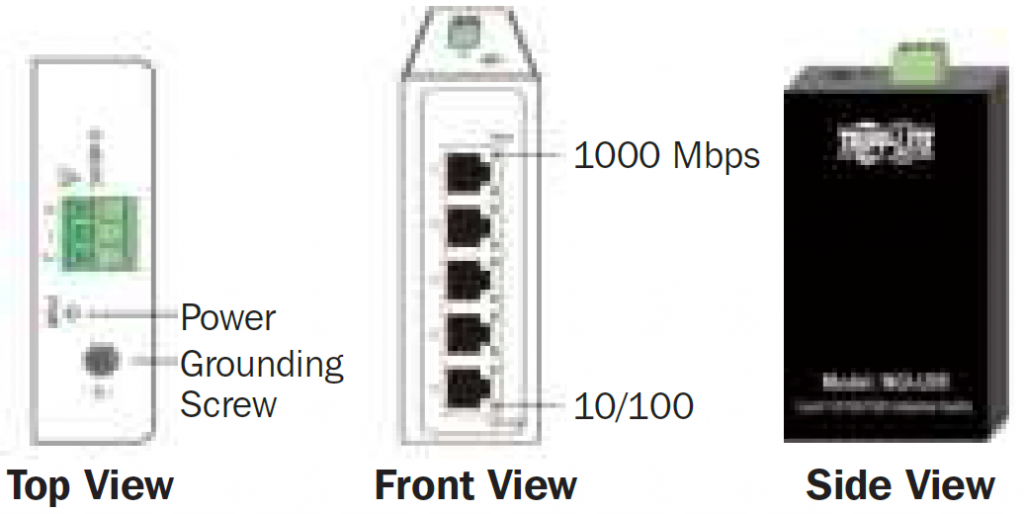
NGI-U055-Port Unmanaged Industrial Gigabit 10/100/1000 Ethernet Switch, Plug and play – Din and Wall Mountable
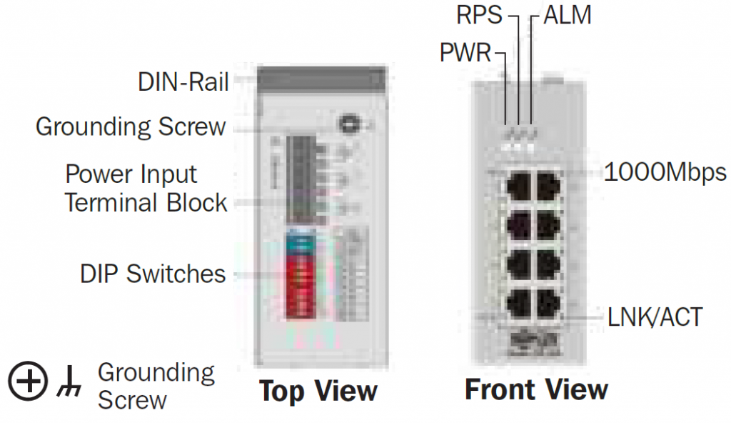
NGI-U088-Port Unmanaged Industrial Gigabit 10/100/1000 Ethernet Switch, Plug and play – DIN Mountable
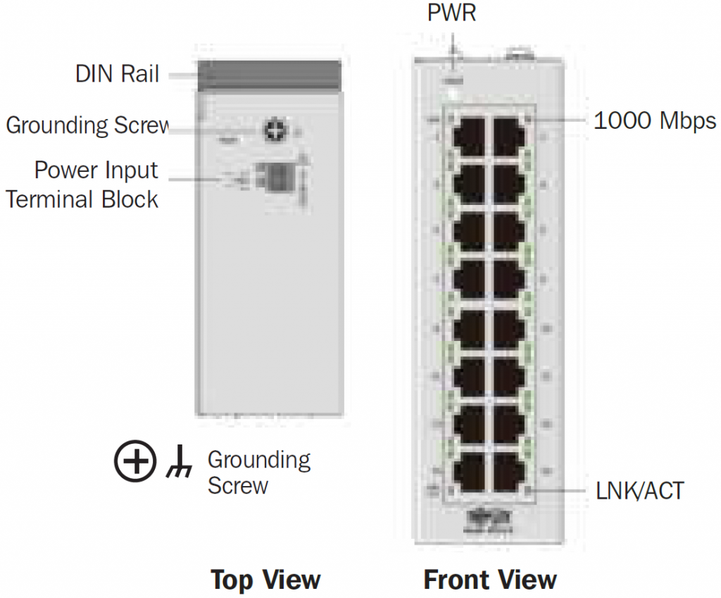
NGI-U1616-Port Unmanaged Industrial Gigabit 10/100/1000 Ethernet Switch, Plug and Play, DIN Mountable
DIN-Rail Mounting/Dismounting Instructions
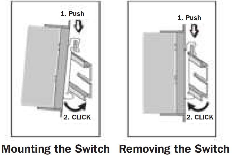
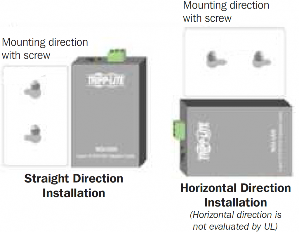
- Mount the switch by using mounting holes on the wall at the appropriate places.

- The switch can be wall mounted either vertically or horizontally.Note: Horizontal mounting is not evaluated by UL.

Wiring Requirements
WARNING: Safety measures should be taken before connecting the power cable. Turn off the power before connecting modules or wires. The correct power supply voltage is listed on the product label. Check the voltage of your power source to make sure you are using the correct voltage. DO NOT use a voltage greater than what is specified on the product label. Calculate the maximum possible current in each power wire and common wire. Observe all electrical codes dictating the maximum current allowable for each wire size. If current exceeds the maximum rating, the wiring can overheat, causing serious damage to your equipment.
Please read and follow these guidelines:
- Use separate paths to route wiring for power and devices. If power wiring and device wiring paths must cross, make sure the wires are perpendicular at the intersection point.Note: Do not run signal or communications wiring and power wiring through the same wire conduit. To avoid interference, wires with different signal characteristics should be routed separately.
- You can use the type of signal transmitted through a wire to determine which wires should be kept separate. Wiring that shares similar electrical characteristics can be bundled together.
- You should separate input wiring from output wiring.
- Be advised that you should label the wiring to all devices in the system.
Wiring Power InputNGI-U05 with 3-Pin Terminal BlockCheck the polarity while connecting. Top view of the Terminal Block is shown in the figure below:
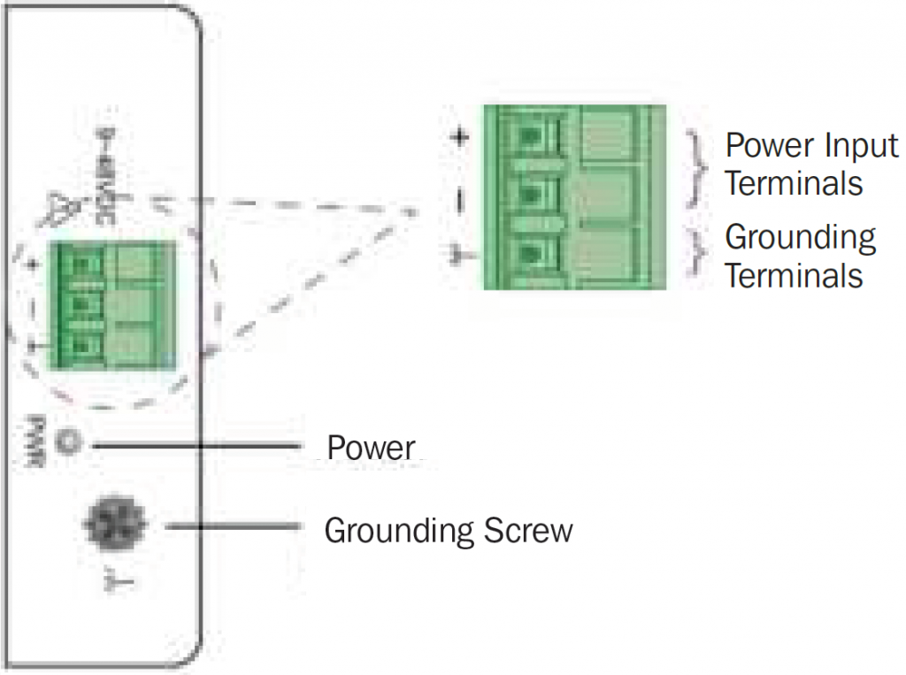
To insert power wire and connect the 9~48VDC at a maximum of 0.5A DC power to the power terminal block, follow these steps:
- Use a flat-head screwdriver to loosen the wire-clamp screws.
- Insert the negative/positive DC wires into the ( – / + ) terminals, respectively.
- Tighten the wire-clamp screws to prevent the wires from loosening.
ATTENTION: Use a power supply from 9~48VDC. The device power shall be supplied by LPS (Limited Power Source) circuit.
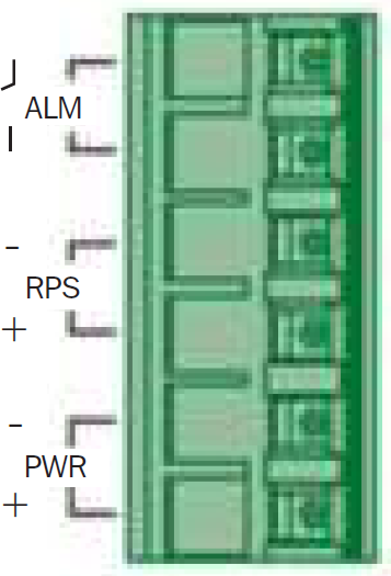
NGI-U08 with 6-Pin Terminal BlockUse “PWR” for the primary power input and “RPS” for the redundant power input.
CAUTION:
- Use copper conductors only.
- Wiring cable temperature should support at least 220°F (105°C).
- Tighten the wire to a torque value of 5 lb.-in.
- The wire gauge for the terminal block should range between 12 and 24 AWG.
To insert power wire and connect the 9~VDC at a maximum of 1A DC power to the NGI-U08 power terminal block, follow these steps:
- Use a flat-head screwdriver to loosen the wire-clamp screws.
- Insert the negative/positive DC wires into the PWR-/PWR+ terminals, respectively.
- Tighten the wire-clamp screws to prevent the wires from loosening.
ATTENTION: Use a power supply from 9~57VDC for NGI-U08. The device power shall be supplied by LPS (Limited Power Source) circuit.
Wiring the Relay Contact (ALM) – only for device with 6-pin terminal blockThe NGI-U08 (device with 6-pin terminal block) has one set of relay alarm output. This relay contact uses two contacts of the terminal block on the NGI-U08 top panel.The two contacts of the 6-pin terminal block connector are used to detect user-configured events. The two wires attached to the fault contacts form an open circuit when a user-configured event is triggered. If a user-configured event does not occur, the fault circuit remains closed.
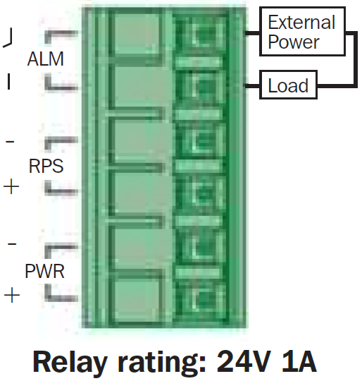
DIP Switch SettingsThe switch supports an “Alarm Relay Output” function. You can connect an alarm light or a buzzer. When events occur that enabled by the DIPs, the switch will operate the relay ON to enable the alarm light or a buzzer. The load can be an “alarm light” a “buzzer” or other equipment.
User configurable switches:
- PWR or RPS “DIP ON”: when there is a power loss, the switch will operate the “Relay ON.” If connecting only to single power and a power loss occurs, the switch system will shut down and will not operate the “Relay ON.”
- Port 1~ Port X “DIP ON”: when the port “Link is down,” the switch will operate the “Relay ON.” It can help to inform the link-down events that happened.
- It is not required to connect alarm equipment to the Alarm Relay output port. The switch has an ALARM LED indicator on the front panel.
- Default settings for the DIP switch are set to OFF positions.
NGI-U08 DIP Switches
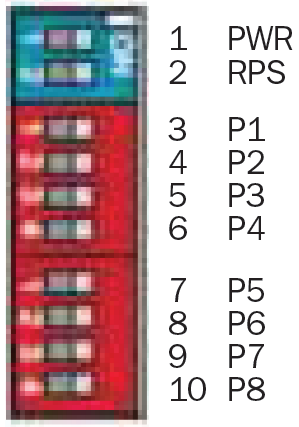
| PWR | ON: Primary power alarm reporting is enabled |
| OFF: Primary power alarm reporting is disabled | |
| RPS | ON: Redundant power alarm reporting is enabled |
| OFF: Redundant power alarm reporting is disabled | |
| P1 | ON: Port 1 link alarm reporting is enabled |
| OFF: Port 1 link alarm reporting is disabled | |
| P2 | ON: Port 2 link alarm reporting is enabled |
| OFF: Port 2 link alarm reporting is disabled | |
| P3 | ON: Port 3 link alarm reporting is enabled |
| OFF: Port 3 link alarm reporting is disabled | |
| P4 | ON: Port 4 link alarm reporting is enabled |
| OFF: Port 4 link alarm reporting is disabled | |
| P5 | ON: Port 5 link alarm reporting is enabled |
| OFF: Port 5 link alarm reporting is disabled | |
| P6 | ON: Port 6 link alarm reporting is enabled |
| OFF: Port 6 link alarm reporting is disabled | |
| P7 | ON: Port 7 link alarm reporting is enabled |
| OFF: Port 7 link alarm reporting is disabled | |
| P8 | ON: Port 8 link alarm reporting is enabled |
| OFF: Port 8 link alarm reporting is disabled |
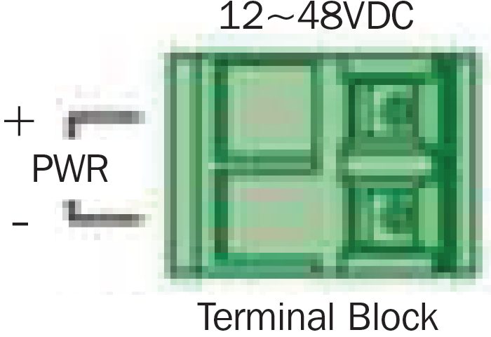
NGI-U16 with 2-Pin Terminal Block
You can use “PWR” for power input.Top view of the Terminal Block is shown in the figure at right.
CAUTION:
- Use copper conductors only.
- Wiring cable temperature should support at least 220°F (105°C).
- Tighten the wire to a torque value 4.5 lb.-in.
- The wire gauge for the terminal block should range between 12 and 24 AWG.
To insert power wire and connect the 12~48VDC at a maximum of 1.5A DC power to the power terminal block, follow these steps:
- Use a flat-head screwdriver to loosen the wire-clamp screws.
- Insert the negative/positive DC wires into the PWR-/PWR+ terminals, respectively.
- Tighten the wire-clamp screws to prevent the wires from loosening.
ATTENTION: Use a power supply from 12~48VDC. The device power shall be supplied by LPS (Limited Power Source) circuit.
Cabling
Connect one end of an Ethernet/RJ45 cable into the Ethernet port of the NGI-U05, NGI-U08 or NGI-U16. Connect the other end to a network device. Ports 1 through 5, 8 or 16 on the switch support Fast Ethernet, as well as Gigabit Ethernet (10/100/1000Base-T ports).All the RJ45 ports on the NGI-U05 and NGI-U08 support auto- negotiation and Auto MDI/MDI-X to eliminate the need for crossover cabling.
Note: Category 5e or above cable should be used.
Grounding the NGI Series Switch ModelsGrounding and wire routing help limit the effects of noise due to electromagnetic interference (EMI). Run the ground connection from the ground screw to the grounding surface prior to connecting devices.
ATTENTION: This product is intended to be mounted to a well-grounded mounting surface, such as a metal panel.
LED Indicators
| NGI-U05 | ||
| PWR
(Green) |
Illuminated | Power On by terminal block PWR |
| Off | Terminal block PWR failed or is not available | |
| 1000
(Green) |
Illuminated | Link speed at 1000 Mbps |
| Blinking | Data is transmitting/receiving | |
| Off | Link speed at 10/100 Mbps or link failed | |
| 10/100
(Green) |
Illuminated | Copper port link-up 10/100 Mbps |
| Blinking | Data is transmitting/receiving | |
| Off | Link speed at 1000 Mbps or link failed |
| NGI-U08 | ||
| PWR
(Green) |
Illuminated | Power On by terminal block PWR or DC jack |
|
Off |
Terminal block PWR/DC jack failed or is not available | |
| RPS
(Green) |
Illuminated | Power on by terminal block RPS |
| Off | Terminal block RPS failed or is unavailable | |
| ALM
(Red) |
Illuminated | PWR/RPS failed or unavailable |
| Off | No power or DIP function is disabled | |
| 1000M
(Green) |
Illuminated | Link speed at 1000 Mbps |
| Off | Link speed at 10/100 Mbps | |
| LNK/ACT
(Green) |
Illuminated | Copper port link-up 1000 Mbps |
| Blinking | Data is transmitting/receiving | |
| Off | Port disconnected or link failed |
| NGI-U16 | ||
| PWR
(Green) |
Illuminated | Power is supplied to switch |
| Off | Power off or failed | |
| 1000
(Green) |
Illuminated | Link speed at 1000 Mbps |
| Off | Link speed at 10/100 Mbps | |
| LNK/ACT
(Green) |
Illuminated | Ethernet link-up |
| Blinking | Data is transmitting/receiving | |
| Off | Port disconnected or link failed |
ATTENTION: This device complies with Part 15 of the FCC rules. Operation is subject to the following conditions:
- This device may not cause harmful interference.
- This device must accept any interference received including interference that may cause undesired operation.
ATTENTION: If the equipment is used in a manner not specified, the protection provided by the equipment may be impaired.
Specifications
| Model | NGI-U05 | NGI-U08 | NGI-U16 |
| Power | |||
| Input Voltage | Single power input 9~48VDC/0.5A | Dual power inputs 9~57VDC/1A | Single power input 12~48VDC/1.5A |
| Connection | 3-pin terminal block | 6-pin terminal block | 2-pin terminal block |
| Reverse Polarity Protection | Present | Present | Present |
| Power Consumption (System Only) | 4W | 5W | 12W |
| Grounding Screw | Present | Present | Present |
| Interface | |||
| RJ45 | 5 x 10/100/ 1000Base-T Supports
auto-negotiation, Auto MDI/MDI-X, Full/Half Duplex and Flow Control |
8 x 10/100/ 1000Base-T Supports
auto-negotiation, Auto MDI/MDI-X, Full/Half Duplex and Flow Control |
16 x 10/100/ 1000Base-T Supports
auto-negotiation, Auto MDI/MDI-X, Full/Half Duplex and Flow Control |
| Fiber Ports | – | – | – |
| LED Indications | PWR (Green): for power
10/100 (Green): for ports 1 to 5 Ethernet speed 10/100 Mbps & data transmitting/ receiving 1000 (Green): for ports 1 to 5 Ethernet speed 1000 Mbps & data transmitting/ receiving |
PWR (Green): for power by terminal block PWR
RPS (Green): for power by terminal block RPS ALM (Red): for PWR & RPS fails and RJ45 Port link down 1000 (Green): for ports 1 to 8 Ethernet speed 1000 Mbps LNK/ACT (Green): for data transmitting / receiving |
PWR (Green): for power
1000 (Green): for ports 1 to 16 Ethernet speed 1000 Mbps LNK/ACT (Green): for ports 1 to 16 data transmitting/ receiving |
| Model | NGI-U05 | NGI-U08 | NGI-U16 |
| Alarm Relay Output | – | 1 Alarm relay output for power loss and port link down | – |
| Environmental | |||
| Operating Temperature | -40°F to 167°F (-40°C to 75°C) | -40°F to 167°F (-40°C to 75°C) | -40°F to 167°F (-40°C to 75°C) |
| Storage Temperature | -40°F to 185°F (-40°C to 85°C) | -40°F to 185°F (-40°C to 85°C) | -40°F to 185°F (-40°C to 85°C) |
| Operating Humidity | 5 to 95% RH
(non-condensing) |
5 to 95% RH
(non-condensing) |
5 to 95% RH
(non-condensing) |
| Storage Humidity | 5 to 95% RH
(non-condensing) |
5 to 95% RH
(non-condensing) |
5 to 95% RH
(non-condensing) |
| Operating Altitude | 6500 ft. (2000 m) | 6500 ft. (2000 m) | 6500 ft. (2000 m) |
| Regulatory Approvals | |||
| EMI/EMC | FCC Part 15
EN 55011 EN 55032 EN 55024 |
FCC Part 15
EN 55011 EN 61000-6-4 EN IEC 61000-6-2 EN 55032 EN 55024 |
FCC Part 15
EN 55011 EN 61000-6-4 EN 61000-6-2 EN 55032 EN 55024 |
Warranty and Product Registration
3-Year Limited WarrantySeller warrants this product, if used in accordance with all applicable instructions, to be free from original defects in material and workmanship for a period of three (3) years from the date of initial purchase. If the product should prove defective in material or workmanship within that period, Seller will repair or replace the product, at its sole discretion.
THIS WARRANTY DOES NOT APPLY TO NORMAL WEAR OR TO DAMAGE RESULTING FROM ACCIDENT, MISUSE, ABUSE OR NEGLECT. SELLER MAKES NO EXPRESS WARRANTIES OTHER THAN THE WARRANTY EXPRESSLY SET FORTH HEREIN. EXCEPT TO THE EXTENT PROHIBITED BY APPLICABLE LAW, ALL IMPLIED WARRANTIES, INCLUDING ALL WARRANTIES OF MERCHANTABILITY OR FITNESS, ARE LIMITED IN DURATION TO THE WARRANTY PERIOD SET FORTH ABOVE; AND THIS WARRANTY EXPRESSLY EXCLUDES ALL INCIDENTAL AND CONSEQUENTIAL DAMAGES. (Some states do not allow limitations on how long an implied warranty lasts, and some states do not allow the exclusion or limitation of incidental or consequential damages, so the above limitations or exclusions may not apply to you. This warranty gives you specific legal rights, and you may have other rights which vary from jurisdiction to jurisdiction.)
WARNING: The individual user should take care to determine prior to use whether this device is suitable, adequate or safe for the use intended. Since individual applications are subject to great variation, the manufacturer makes no representation or warranty as to the suitability or fitness of these devices for any specific application.
Product RegistrationVisit tripplite.com/warranty today to register your new Tripp Lite product. You’ll be automatically entered into a drawing for a chance to win a FREE Tripp Lite product!*No purchase necessary. Void where prohibited. Some restrictions apply. See website for details.
WEEE Compliance Information for Tripp Lite Customers and Recyclers (European Union)
Under the Waste Electrical and Electronic Equipment (WEEE) Directive and implementing regulations, when customers buy new electrical and electronic equipment from Tripp Lite, they are entitled to:
- Send old equipment for recycling on a one-for-one, like-for-like basis (this varies depending on the country)
- Send the new equipment back for recycling when this ultimately becomes waste
FCC Notice, Class B
This device complies with part 15 of the FCC Rules. Operation is subject to the following two conditions: (1) This device may not cause harmful interference, and (2) this device must accept any interference received, including interference that may cause undesired operation.
Note: This equipment has been tested and found to comply with the limits for a Class B digital device, pursuant to part 15 of the FCC Rules. These limits are designed to provide reasonable protection against harmful interference in a residential installation. This equipment generates, uses and can radiate radio frequency energy and, if not installed and used in accordance with the instructions, may cause harmful interference to radio communications. However, there is no guarantee that interference will not occur in a particular installation. If this equipment does cause harmful interference to radio or television reception, which can be determined by turning the equipment off and on, the user is encouraged to try to correct the interference by one or more of the following measures:
- Reorient or relocate the receiving antenna.
- Increase the separation between the equipment and receiver.
- Connect the equipment into an outlet on a circuit different from that to which the receiver is connected.
- Consult the dealer or an experienced radio/TV technician for help.
Any changes or modifications to this equipment not expressly approved by Tripp Lite could void the user’s authority to operate this equipment.Use of this equipment in life support applications where failure of this equipment can reasonably be expected to cause the failure of the life support equipment or to significantly affect its safety or effectiveness is not recommended.Tripp Lite has a policy of continuous improvement. Specifications are subject to change without notice. Photos and illustrations may differ slightly from actual products.
1111 W. 35th Street, Chicago, IL 60609 USA • tripplite.com/support
![]()
References
[xyz-ips snippet=”download-snippet”]