![]()
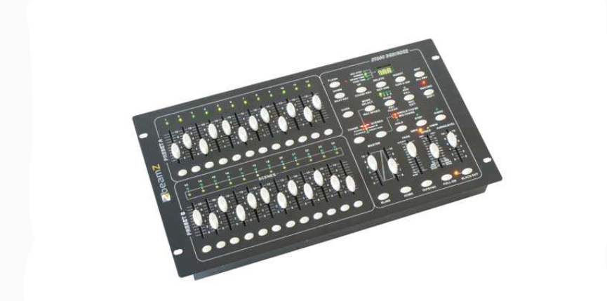
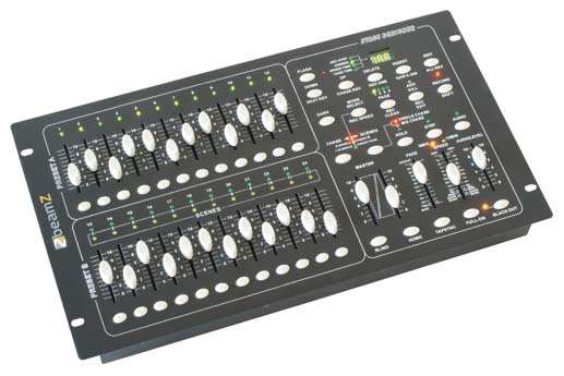
DMX-024PRO controller Scene SetterRef. nr.: 154.062
INSTRUCTION MANUAL
Congratulations to the purchase of this Beamz light effect. Please read this manual thoroughly prior to using the unit in order to benefit fully from all features.Read the manual prior to using the unit. Follow the instructions in order not to invalidate the warranty. Take all precautions to avoid fire and/or electrical shock. Repairs must only be carried out by a qualified technician in order to avoid electrical shock. Keep the manual for future reference.
- – Prior to using the unit, please ask advice from a specialist. When the unit is switched on for the first time, some smell may occur. This is normal and will disappear after a while.
- – The unit contains voltage carrying parts. Therefore do NOT open the housing.
- – Do not place metal objects or pour liquids into the unit This may cause electrical shock and malfunction.
- – Do not place the unit near heat sources such as radiators, etc. Do not place the unit on a vibrating surface. Do not cover the ventilation holes.
- – The unit is not suitable for continuous use.
- – Be careful with the mains lead and do not damage it. A faulty or damaged mains lead can cause electrical shock and malfunction.
- – When unplugging the unit from a mains outlet, always pull the plug, never the lead.
- – Do not plug or unplug the unit with wet hands.
- – If the plug and/or the mains lead are damaged, they need to be replaced by a qualified technician.
- – If the unit is damaged to such an extent that internal parts are visible, do NOT plug the unit into a mains outlet and DO NOT switch the unit on. Contact your dealer. Do NOT connect the unit to a rheostat or dimmer.
- – To avoid fire and shock hazard, do not expose the unit to rain and moisture.
- – All repairs should be carried out by a qualified technician only.
- – Connect the unit to an earthed mains outlet (220240Vac/50Hz) protected by a 10-16A fuse.
- – During a thunderstorm or if the unit will not be used for a longer period of time, unplug it from the mains. The rule is: Unplug it from the mains when not in use.
- – If the unit has not been used for a longer period of time, condensation may occur. Let the unit reach room temperature before you switch it on. Never use the unit in humid rooms or outdoors.
- – During operation, the housing becomes very hot. Do not touch it during operation and immediately after.
- – To prevent accidents in companies, you must follow the application guidelines and follow the instructions.
- – Secure the unit with an extra safety chain if the unit is ceiling mount. Use a truss system with clamps. Make sure nobody stands in the mounting area. Mount the effect at least 50cm away from inflammable material and leave at least 1-meter space on every side to ensure sufficient cooling.
- – This unit contains high-intensity LEDs. Do not look into the LED light to prevent damage to your eyes.
- – Do not repeatedly switch the fixture on and off. This shortens the life time.
- – Keep the unit out of the reach of children. Do not leave the unit unattended.
- – Do not use cleaning sprays to clean switches. The residues of these sprays cause deposits of dust and grease. In case of malfunction, always seek advice from a specialist.
- – Only operate the unit with clean hands.
- – Do not force the controls.
- – If the unit has fallen, always have it checked by a qualified technician before you switch the unit on again.
- – Do not use chemicals to clean the unit. They damage the varnish. Only clean the unit with a dry cloth.
- – Keep away from electronic equipment that may cause interference.
- – Only use original spares for repairs, otherwise serious damage and/or dangerous radiation may occur.
- – Switch the unit off prior to unplugging it from the mains and/or other equipment. Unplug all leads and cables prior to moving the unit.
- – Make sure that the mains lead cannot be damaged when people walk on it. Check the mains lead before every use for damages and faults!
- – The mains voltage is 220-240Vac/50Hz. Check if power outlet match. If you travel, make sure that the mains voltage of the country is suitable for this unit.
- – Keep the original packing material so that you can transport the unit in safe conditions
 This mark attracts the attention of the user to high voltages that are present inside the housing and that are of sufficient magnitude to cause a shock hazard.
 This mark attracts the attention of the user to important instructions that are contained in the manual and that he should read and adhere to. DO NOT LOOK DIRECTLY INTO THE LENS. This can damage your eyes. Persons who are subject to epileptic attacks should be aware of the effects that this light effect may have on them.The unit has been certified CE. It is prohibited to make any changes to the unit. They would invalidate the CE certificate and their guarantee!NOTE: To make sure that the unit will function normally, it must be used in rooms with a temperature between 5°C/41°F and 35°C/95°F.
 Electric products must not be put into household waste. Please bring them to a recycling centre. Ask your local authorities or your dealer about the way to proceed. The specifications are typical. The actual values can slightly change from one unit to the other. Specifications can be changed without prior notice.
UNPACKING INSTRUCTION
CAUTION! Immediately upon receiving a fixture, carefully unpack the carton, check the contents to ensure that all parts are present, and have been received in good condition. Notify the shipper immediately and retain packing material for inspection if any parts appear damage from shipping or the package itself shows signs of mishandling. Save the package and all packing materials. In the event that a fixture must be returned to the factory, it is important that the fixture be returned in the original factory box and packing.
If the device has been exposed to drastic temperature fluctuation (e.g. after transportation), do not switch it on immediately. The arising condensation water might damage your device. Leave the device switched off until it has reached room temperature.
POWERSUPPLY
On the label on the backside of the controller is indicated on this type of power supply must be connected. Check that the mains voltage corresponds to this, all other voltages than specified, the light effect can be irreparably damaged. The controller must also be directly connected to the mains and may be used. No dimmer or adjustable power supply.
GENERAL DESCRIPTION
This digital DMX ‘scene setter ‘ light controller can control 24 light channels and gives total dimmer control over all 24 outputs. It features 48 easily programmable memories with a storage capacity for 99 different light effect scenes per memory. It can be set on automatic control or on music control via the built-in microphone or via an external audio signal. The speed and fade time for the running light is also selectable. The digital DMX-512 control uses “addresses” for the individual control of the connected light units. These outgoing addresses are pre-set to the numbers 1 to 24.
CONTROLS AND FUNCTIONS

1. PRESET A LED: Indicator LEDs for the setting of the slider controls from section A.2. CHANNEL SLIDERS 1-12: these sliders will adjust the output of channel 1 to 12 from 0 to 100%3. FLASH KEYS 1-12: Press to activate maximum channel output.
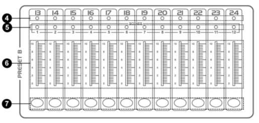
4. PRESET B LED: Indicator LEDs for the setting of the slider controls from section B.5. SCENE LEDS: Indicator LEDs for the active scenes.6. CHANNEL SLIDERS 13-24: these sliders will adjust the output of channel 13 to 24 from 0 to 100%7. FLASH KEYS 13-24: Press to activate maximum channel output.
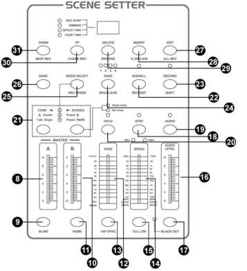
8. MASTER A SLIDER: slider will adjust the output of preset A.9. BLIND KEY: This function takes the channel out of the chase of a program in CHNS /SCENE mode.10. MASTER B: slider control setting the light intensity of channels 13 to 24.11. HOME KEY: This button is used to deactivate the “Blind” function.12. FADE TIME SLIDER: Used to adjust the fade-time.13. TAP SYNC: button to synchronize the STEP rhythm with the music.14. SPEED SLIDER: Used to adjust the chase speed.15. FULL-ON: This function bring overall output to full intensity.16. AUDIO LEVEL: This slider controls the sensitivity of the Audio input.17. BLACKOUT: button switches all outputs to zero. The yellow LED is flashing.18. STEP: This button is used to go to next step or following scene.19. AUDIO: Activates audio sync of chase and audio intensity effects.20. HOLD: This button is used to maintain current scene.21. PARK: in ![]() mode, press it to select SINGLE CHASE or MIX CHASE. In DOUBLE PRESET ,pressing PARK B is same as MASTER B at the maximum. In SINGLE PRESET ,pressing PARK A is same as MASTER A at the maximum.22. ADD / KILL / RECORD EXIT: exit record key. When LED is lit it is in KILL mode, in this mode press any flash key and all channels are zero except the channel selected.23. RECORD / SHIFT: press it to record the step of program. Shift functions only used with other buttons.24. PAGE/REC CLEAR: button to select a memory page from 1 to 4.25. MODE SELECT / REC SPEED: Each tap will activate the operating mode in the order: , Double Preset and Single Preset. Rec Speed: Set the speed of any of the programs chasing in Mix mode.26. DARK: press it to pause whole output, including FULL ON and FLASH.27. EDIT / ALL REV: Edit is used to activate Edit mode. All Rev is to reverse the chasing direction of all programs.28. INSERT / % or 0-255: Insert is to add one step or steps into a scene. % or 0-255 is used to change display value cycle between% and 0-255.29. DELETE / REV ONE: Delete any step of a scene or reverse the chasing direction of any program.30. DELETE / REV ONE: button inverts the running direction of a determined scene.31. DOWN / BEAT REV. : DOWN functions to modify a scene in Edit mode; BEAT REV is used to reverse the chasing direction of a program with regular beat.
mode, press it to select SINGLE CHASE or MIX CHASE. In DOUBLE PRESET ,pressing PARK B is same as MASTER B at the maximum. In SINGLE PRESET ,pressing PARK A is same as MASTER A at the maximum.22. ADD / KILL / RECORD EXIT: exit record key. When LED is lit it is in KILL mode, in this mode press any flash key and all channels are zero except the channel selected.23. RECORD / SHIFT: press it to record the step of program. Shift functions only used with other buttons.24. PAGE/REC CLEAR: button to select a memory page from 1 to 4.25. MODE SELECT / REC SPEED: Each tap will activate the operating mode in the order: , Double Preset and Single Preset. Rec Speed: Set the speed of any of the programs chasing in Mix mode.26. DARK: press it to pause whole output, including FULL ON and FLASH.27. EDIT / ALL REV: Edit is used to activate Edit mode. All Rev is to reverse the chasing direction of all programs.28. INSERT / % or 0-255: Insert is to add one step or steps into a scene. % or 0-255 is used to change display value cycle between% and 0-255.29. DELETE / REV ONE: Delete any step of a scene or reverse the chasing direction of any program.30. DELETE / REV ONE: button inverts the running direction of a determined scene.31. DOWN / BEAT REV. : DOWN functions to modify a scene in Edit mode; BEAT REV is used to reverse the chasing direction of a program with regular beat.
CONNECTIONS AT THE REAR PANEL

1. POWER INPUT: DC 12-18V, 500mA MIN.2. MIDI THRU: Use to transmit MIDI data received on the MIDI IN connector.3. MIDI OUT: transmit MIDI data originated by itself.4. MIDI IN: received MIDI data.5. DMX OUT: DMX output.6. DMX POLARITY SELECT: select the polarity of DMX output.7. AUDIO INPUT: line in music single.100mV-1Vpp.8. REMOTE CONTROL: FULL ON and BLACKOUT are remote controlled using 1/4″ stereo jack.
BASIC FUNCTIONS FOR PROGRAMMING
1) Activation of the programming mode:Keep the RECORD/SHIFT button pushed in and press in sequence the flash buttons 1, 5, 6 and 8. These buttons are located just below the slider controls in the upper row PRESET A. Release the RECORD/SHIFT button. The red programming LED should light up.
2) Exit the programming mode:Hold the RECORD/SHIFT button down and press simultaneously the REC/EXIT button. The red programming LED goes off.
3) Erasing all programs (be careful !):Activate the programming mode as described above in step 1. Hold the RECORD/SHIFT button down and press in sequence the flash buttons 1, 3, 2 and 3 in the section PRESET A. Release the RECORD/SHIFT button. All stored running light scenes are now erased from the ROM. All LEDs flash to confirm. Press the RECORD/SHIFT and the REC/EXIT buttons at the same time to leave the programming mode.
2) Erasing the RAM:The RAM is used as an intermediate memory for a number of running light scenes during the programming process. If you make a mistake during the programming, you can erase the RAM. Activate the programming mode as described in step 1. Hold the RECORD/SHIFT button down while pressing the REC/CLEAR button. All LEDs flash once to indicate that the RAM has been erased.
PROGRAMMING RUNNING LIGHT PATTERNS (SCENES)
1) Activate the programming mode as described in the Basic Functions.2) Select the mode 1-24 single (the green LED lights up) via the MODE SELECT button. In this mode, you can use all 24 channels.3) Push the MASTER slider controls A and B to their maximum positions. Note: Control A completely up and control B completely down.4) Set the required light position via the slider controls 1 to 24.5) Press the RECORD/SHIFT button once to store this position in the RAM.6) Repeat steps 4 and 5 with different positions of the slider controls in order to get an optimal light effect. You can store up to 99 steps per memory.7) The programmed steps must now be transferred from the RAM to the ROM. Proceed as follows: Select a memory page (1 to 4) via the PAGE/REC CLEAR button. Hold the RECORD/SHIFT button down and press one of the flash buttons 1 to 13 in section PRESET B. You can store up to 99 steps per memory. There are in total 4 pages with 12 memories each.8) Exit the programming mode (press RECORD/SHIFT and REC EXIT buttons). The red programming LED must go off.
EXAMPLE: PROGRAMMING A LINEAR RUNNING LIGHT EFFECT
1) Switch the programming mode on (press RECORD/SHIFT and buttons 1, 5, 6 and 8).2) Set both MASTER slider controls to the maximum (A upwards, B downwards).3) Select mode 1-24 single via the MODE SELECT button (the green LED lights up).4) Push the control 1 to 10 (maximum) and press the RECORD/SHIFT button once.5) Push the controls 1 to zero and 2 to maximum and press RECORD/SHIFT again6) Push controls 2 to zero and 3 to maximum and press RECORD/SHIFT again.7) Repeat these steps up to control 24.8) Select a memory page (1 to 4) via the PAGE/REC CLEAR button.9) Save the running light effect in this page by pressing one of the flash buttons in section PRESET B (1 to 12). Use e.g. button number 1.10) Leave the programming mode by pressing simultaneously the RECORD/SHIFT and REC EXIT buttons.
PLAYING A RUNNING LIGHT PATTERN
1) Select the mode CHASE/SCENES via the MODE SELECT button. The red LED lights up.2) Push the control of the appropriate channel (memory) from section PRESET B to the top. In our example it was flash button 1. This triggers the steps which are stored in that memory. If the appropriate slider control was already in the upper position, it is necessary to pull it down first and push it up again to trigger the pattern.
ERASING A RUNNING LIGHT PATTERN
1) Activate the programming mode (press RECORD/SHIFT and buttons 1, 5, 6 and 8 –the top row).2) Select the required page (1 to 4) via the PAGE/REC CLEAR button.3) Hold the RECORD/SHIFT button down and press quickly TWICE the appropriate flash button from section PRESET B in which the pattern to be erased is stored.4) Release the RECORD/SHIFT. All indicator LEDs light up to confirm.
CHANGING A RUNNING LIGHT PATTERN
A running light pattern (scene) can contain up to 99 steps. These steps can be changed or erased later. You can also addsteps later. Each ‘step’ is a determined setting of the variable light intensity (0-100%) of 24 lamps or groups of lamps.
Erasing a particular step:
1) Activate the programming mode (press RECORD/SHIFT and simultaneously 1, 5, 6, and 8).2) Select the required page via the PAGE button.3) Press the MODE SELECT button until the red LED lights up (CHASE-SCENES).4) Hold the EDIT button down and press at the same time the flash button of the appropriate running light pattern (flash buttons in the lower row of the section PRESET B).6) Release the EDIT button and select via the STEP button the step to be erased.7) Press the DELETE button and the selected step will be erased from the memory.8) Leave the programming mode by holding the RECORD/SHIFT button down while pressing twice the REC/EXIT button.
Adding steps:1) Activate the programming mode (press RECORD/SHIFT and simultaneously in sequence 1, 5, 6, and 8).2) Select the required page via the PAGE button.3) Press the MODE SELECT button until the red LED lights up (CHASE-SCENES).4) Hold the EDIT button down and press at the same time the flash button of the appropriate running light pattern (flash buttons in the lower row of the section PRESET B).5) Release the EDIT button and select via the STEP button the step just after the step to be added.6) Set the required light position via the slider controls, press the RECORD/SHIFT button and then the INSERT button.7) If required, repeat steps 5 and 6 to add more steps.8) Hold the RECORD/SHIFT button down and press twice the REC/EXIT button to leave the programming mode.
Changing steps:1) Activate the programming mode (press RECORD/SHIFT and simultaneously in sequence 1, 5, 6, and 8).2) Select the required page via the PAGE button.3) Press the MODE SELECT button until the red LED lights up (CHASE-SCENES).4) Hold the EDIT button down and press at the same time the flash button of the appropriate running light pattern (flash buttons in the lower row of the section PRESET B).5) Select the required step via the STEP button.6) Now you can change the light intensity of the lamps as follows: hold the DOWN button pressed while pressing the flash button of the channel that you want to change. The display shows which setting has been selected. (0 – 255 is equivalent to 0 – 100%)7) Hold the RECORD/SHIFT button down and press twice the REC/EXIT button to leave the programming mode.
MUSIC CONTROL
Connect an audio source to the RCA input at the rear side (100mV p-p). Switch the music control on via the AUDIO button. The green LED lights up. Set the required effect via the slider control AUDIO LEVEL.
STORING A RUNNING LIGHT SPEED
1) Switch the music control off.2) Select the required pattern via the PAGE button and the appropriate slider control of the section PRESET B.3) Press the MODE SELECT button until the red LED lights up (CHASE-SCENES).4) Select the MIX CHASE mode via the PARK button (the yellow LED lights up)5) Set the running light speed via the SPEED slider control or press in the right rhythm twice the TAP SYNC button. You can repeat this until you have found the correct speed.6) Store this speed setting in the memory by holding the REC SPEED button down while pressing the flash button of the appropriate pattern. The slider control that triggers the pattern, must be in the upper position.
ERASING A PROGRAMMED SPEED
1) Switch off the music control.2) Select the required pattern via the PAGE button and the appropriate slider control of the section PRESET B. Set the slider control completely to the top.3) Press the MODE SELECT button until the red LED lights up (CHASE-SCENES).4) Select the MIX CHASE mode via the PARK button (the yellow LED lights up).5) Push the slider control SPEED completely down.6) Hold the REC SPEED button down while pressing the flash button of the appropriate pattern. The fixed speed setting is now erased.
CHANGING THE RANGE OF THE SPEED CONTROL
This slider control has two adjustable control ranges: 0.1 seconds to 5 minutes and 0.1 seconds to 10 minutes. Hold the RECORD/SHIFT button down and press three times in sequence the flash button number 5 (from the top row) to set the range to 5 minutes, or three times the flash button 10 for the 10 minutes setting. The selected range is indicated by the yellow LEDs just above the SPEED control.
EXPLANATION OF SOME SPECIAL FUNCTIONS
Note: When the scene setter is switched on, the BLACK OUT function is automatically activated. All outputs are set to zero so that the connected light effects do not work. Press the BLACK OUT button to leave this mode.
Fade time:The FADE control sets the fading time between the different light positions.
Single Mode:In single mode all running light programs will be played in sequence. Select the CHASE-SCENES mode via the MODE SELECT button (red LED) and the SINGLE CHASE mode via the PARK button (yellow LED). Make sure that the audio control is switched off. The SPEED control sets the speeds of all patterns.
Mix Mode:Multiple play of the stored patterns. Select CHASE-SCENES via the MODE SELECT button (red LED) and MIX CHASE via the PARK button (yellow LED). Make sure that the audio control is switched off and set the speed of the light effects individually via the SPEED control.
Indications on the display:The display shows the different settings and pattern numbers. You can choose between the display of the DMX value (0 to 255) or a percentage (0 to 100%) of the light setting. Hold the RECORD/SHIFT button down while pressing the INSERT/% or 0-255 button. Set one of the slider controls 1 to 24 in the upper position and check the display. If required, repeat these steps. The minutes and seconds are indicated on the display by two dots. E.g. 12 minutes and 16 seconds are displayed as 12.16.. If the time is below 1 minute, it is displayed by 1 dot e.g. 12.0 is 12 seconds and 5.00 is 5 seconds.
Blind function:During automatic play of a running light pattern, it is possible to switch off a particular channel and to control that channel manually. Hold the BLIND button down while pressing the flash button of the channel that you wish to switch off temporarily. To switch the channel on again, proceed in the same way.
DIFFERENT FUNCTIONS FOR THE MIDI PROTOCOL
Switching on the MIDI input function:1) Hold the RECORD/SHIFT button down.2) Press three times the flash button no. 1 in the PRESET A section.3) Release the buttons. The display shows now [Chl]4) Select via one of the flash buttons 1 to 12 in section PRESET B the pattern to which you wish to add the MIDI file.
Switching on the MIDI output function:1) Hold the RECORD/SHIFT button down.2) Press three times the flash button no. 2 in the PRESET A section.3) Release the buttons. The display shows now [Ch0].4) Select via one of the flash buttons 1 to 12 in section PRESET B the pattern from where you wish to switch on the MIDI output function.
Switching off the MIDI in- and output functions1) Hold the RECORD/SHIFT button down.2) Press the REC/EXIT button once.3) Release both buttons. The display show now 0.00.
Downloading a MIDI control file:1) Hold the RECORD/SHIFT button down.2) Press three times the flash button no. 3 in the PRESET A section.3) Release both buttons. The display shows now [IN].4) While downloading the data, all running light functions are temporarily switched off.5) The control protocol downloads the data from address 55Hex under the file name DC1224.bin.
Uploading a MIDI control file:1) Hold the RECORD/SHIFT button down.2) Press three times the flash button no. 4 in the PRESET A section.3) Release both buttons. The display shows now [OUT].4) While uploading the data, all running light functions are temporarily switched off.5) The control protocol uploads the data to address 55Hex under the file name DC1224.bin.
Attention!1. To retain your programs from loss, this unit must be powered not less than two hour every month.2. The Segment Display shows “LOP” if the voltage is too low.
TECHNICAL SPECIFICATION
Power input : DC12~20V, 500mADMX connector : 3-polig XLR outputMIDI connector : 5-pin DINAudio Input: RCA, 100mV-1V (pp)Dimensions per unit: 483 x 264 x 90mmWeight (per unit) : 4.1 kg
The specifications are typical. The actual values can slightly change from one unit to the other. Specifications can be changed without prior notice.
![]()
 Declaration of Conformity
Manufacturer:TRONIOS BVBedrijvenpark Twente 4157602 KM – ALMELO+31(0)546589299+31(0)546589298The Netherlands
Product number:154.062
Product Description:DMX 024 PRO Controller Scene Setter
Trade Name:BEAMZ
Regulatory Requirement:EN 60065EN 55013EN 55020EN 61000-3-2/-3-3
The product meets the requirements stated in Directives 2006/95 and 2004/108/EC and conforms to the above-mentioned Declarations.Almelo,29-07-2015
Name : B. Kosters (Controller regulations)Signature :

Specifications and design are subject to change without prior notice..www.tronios.comCopyright © 2015 by TRONIOS the Netherlands
References
[xyz-ips snippet=”download-snippet”]