
![]() Owners Manual
Owners Manual
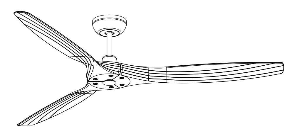
Solara+WiFi (3LN60+WiFi)
This instruction contains 11 pages:
Page 1: Read Safety instructionsPage 2: Unpack and inspect parts containedPage 3~4: Notes before installation and Hanging system installation /Blade installationPage 5: Wire connectionPage 6: Canopy installation /Remote Transmitter assemblyPage 7: Operational instruction / TroubleshootingPage 8~9: Remote Pairing ProcessPage 10~11: WiFi Pairing![]() Toll-Free: 1-855-676-7247
Toll-Free: 1-855-676-7247
Net weight :5.2 KGS.11.4 LBS.
WARNING: Read and follow these instructions carefully and be mindful of all warnings shown throughout.
READ AND SAVE THESE INSTRUCTIONS
WARNING: TO REDUCE THE RISK OF FIRE, ELECTRICAL SHOCK, OR INJURY TO PERSONS, PLEASE OBSERVE THE FOLLOWING:
- To ensure the success of the installation, be sure to read the instructions and review the diagrams thoroughly before beginning.
- To avoid possible electric shock, be sure electricity is turned off at the main power box before wiring. All electrical connections must be made in accordance with local codes, ordinances and/or the National Electric Code. If you are unfamiliar with the methods of installing electrical wiring and products, require the services of a qualified and licensed electrician as well as someone who can check the strength of the supportive ceiling members and make the proper installations and connections.
- Make sure that your installation site will not allow rotating fan blades to come in contact with any object when fan is in operation. Blades must mounted at least 7 feet from the floor.
- If possible, mount ceiling fan on a ceiling joist – the joist must be able to support the motion and weight of the moving fan. If the fan will be mounted on a ceiling outlet box, a 4” x 2-1/8″ deep METAL octagon box is required ; one UL listed as ” suitable for fan support”. The box and its supporting members must not be able to twist or work loose. DO NOT USE PLASTIC BOXES. Installation on a concrete ceiling should be performed by qualified personnel.
- Blades should be attached after motor housing is hung and in place. Fan motor housing should be kept in carton until ready to be installed to protect its finish. If you are installing more than one ceiling fan, make sure that you do not mix fan blade sets.
- After making electrical connections, spliced conductors should be turned upward and pushed carefully up into outlet box. The wires should be spread apart with the grounded conductor and the equipment – grounding conductor on one side of the outlet box and the * HOT ” wires on the opposite side.
- Electrical diagrams are for reference only. Light kits that are not packed with the fan must be UL/ETL listed and should be installed per the light kit’s installation instructions.
- After fan is completely installed, check to make sure that all connections are secured to prevent fan from falling and/or causing damage or injury.
- The fan can be made to work immediately after installation. There is no need to oil your fan. The motor has permanently lubricated bearings.
- The fan must be turned off and stopped before reversing fan direction.
- The fan is for downrod mount only.
- This fan is reversible.
- This fan is controlled by remote.
- This fan is suitable for damp location use.
“Special note: All green grounding wire(s) from fan must be attached to house Ground/Earth wire to prevent flickering of LED.”
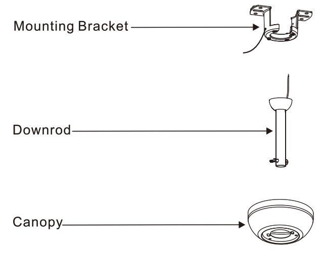
Unpack and inspect fan carefully to be certain all contents are included.
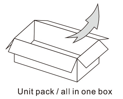
Unpack (Fan & Blades packed in one Box)
 Hardware Bag
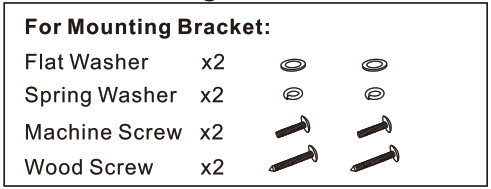
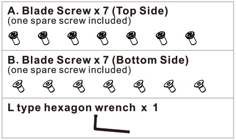 Warning :Bag A : for top blade by Phillips screwdriverBag B : for bottom blade by haxagon wrench see Blade assembly in Page 3
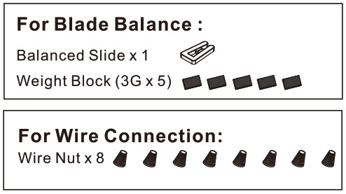

WARNING: BLADES SHOULD BE AT LEAST 7 FEET FROM FLOOR
Note 1:Turn off power at breaker box to avoid possible electrical shock.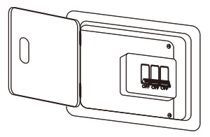 Note 2:Use metal outlet box suitable for fan support. Outlet box must support 35 lbs min.
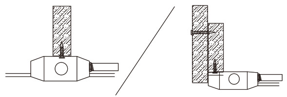
HANGING SYSTEM INSTALLATION
Installing mounting bracket to ceiling outlet box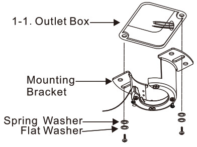 1-1. Install mounting bracket outlet box on ceiling by using screws included with the outlet box and washers from the hardware bag.
 1-2. Loosen the screws at mounting bracket. Do not remove.
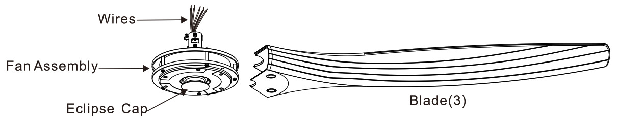
BLADE INSTALLATION
*Use styrofoam as cushion for this step.Special Note: Top blade screw are from Bag “A” using Phillips screw driver. Bottom blade screws are from bag “B” using L Hexagon Wrench.
*Place the fan assembly on Styrofoam with yoke up.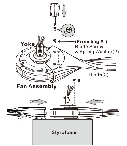 Attach blades to fan assembly by using screws (2) & spring washer (2) provided from hardware bag marked “A” on top of fan assembly.*Make sure the label “THIS SIDE UP” must be on the top side. (Facing the ceiling)
*Turning the fan assembly upside (Eclipse cap up).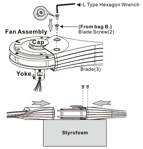 Attach screws (2) on bottom of fan assembly provided from hardware bag marked “B” by suing L Type Hexagon Wrench provided from hardware bag. (*Repeat until all 3 blades are installed firmly.)
*Note: Make sure all blade washers & screws are tightened to avoid operation noise.
DOWNLOAD INSTALLATION
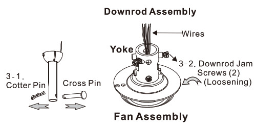 3-1. Remove cross pin and cotter pin from sownrod.3.2. Loosen 2 downrod jam screws at yoke.
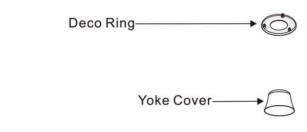
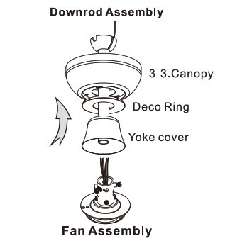 3-3. As shown above, insert yoke cover, deco ring, canopy onto downrod.
 3-4. Insert the lead wires through the downrod assembly.
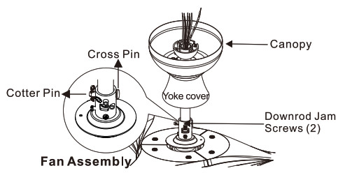 3-5. Insert Downrod assembly into and attach the cross pin through yoke & downrod, secure with cotter pin.
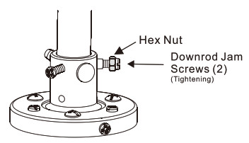 3-6. Make sure the position of the Hex nut must be on side of jam screw head, before tighten jam screw.3-7. Tighten 2 jam screws to secure downrod.
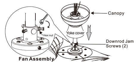 3-8. Use spanner to tighten the Hex nut, so the jam screw will not loose.3-9. Pull down the yoke cover to cover yoke.
HANGING THE FAN ONTO MOUNTING BRACEKET
4-1. Lift fan assembly onto mounting bracket.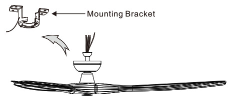 4-2. Rotate fan so that the groove on the ball engages the ridge in the mounting bracket.
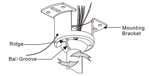
WIRE CONNECTION
5-1. Verify that serial Number & Model Number match on the Receiver and TransmitterNOTICE:Many remote sets for DC fans look the same. This remote set is pre-paired and labeled at the factory, please note the following before operation:1a. The Remote Model Number on transmitter and receiver must be the same.1b. The Remote Serial Number will be the same on a pre-paired remote set. If itis different, it will need to be paired (See page 8)2. The Fan Model Number label must be the same as the fan’s model number in front page (3LN60) for proper operation (There is no Fan Model Number on transmitter. )3. Do not mix the remote sets if you are installing more than one fan.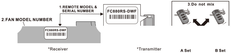 5-2. Insert receiver into mounting bracketNote: Do not squeeze all the wires while inserting the receiver into the mounting bracket.
 5-3. Making electrical wire connectionThe standard lead wire is 54″ long. You may need to cut all 5 lead wires (from motor) to proper length & strip them for wire connection to make it easier for Canopy installation.
Follow diagram below and make sure that all exposed wires are secured inside wire nuts.Note : Wires from house may vary in color. If the house wires do NOT include a ground wire (green) AND the optional #630 LED Light Kit is being installed, to prevent flickering, this unit must be grounded/earthed to the home’s ground/earth; please consult an electrician. After wiring is completed, gently push wires into junction box with wire nuts pointing upward.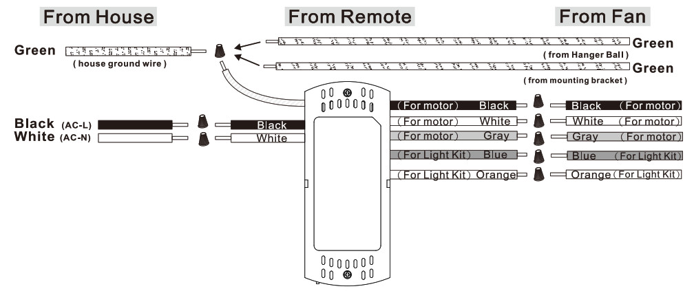
“ Special note: All Green grounding wires, from Hanger ball/Mounting bracket/Receiver, must be well attached to House Ground/Earth to prevent flickering of LED. ”
CANOPY INSTALLATION
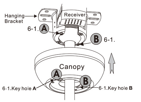
Note: Two screws are installed on mounting bracket for canopy installation.6-1. Push canopy up until the two pre-screwed screws on the mounting bracket are engaged with the two key holes on canopy.6-2. Before rotating the canopy, make sure Key hole A & B of the canopy correspond toA&B positions of the hanging bracket.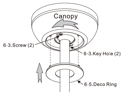
6-3. Rotate canopy slightly until the two pre-installed screw heads are engaged in the narrow end of key holes.6-4.Tighten both screws. 6-5. Aligning the nubs from Deco Ring to 3 holes on the canopy, push Deco Ring up and snap into the canopy.
REMOTE TRANSMITTER ASSEMBLY
![]()
7-1.Install the batteryRemove the back cover and install the 12V battery. (Included from remote box)![]()
7-2.Check the dip switch position (Original dip switch is on Dimming position) Set dip switch in DIMMER position for LED dimming. Set dip switch in ON position for LED ON/OFF only.7-3. Re-install the back cover.![]() Turn on power at breaker box, the fan is ready for operation! (The receiver will have beep sound)
Turn on power at breaker box, the fan is ready for operation! (The receiver will have beep sound)
OPERATIONAL INSTRUCTION
 All the button pressed will have a Beep sound and the red indicator light will turn on.8-1. Press
 ![]() button to turn the fan ON/OFF.Warning: DO NOT PRESS THE
button to turn the fan ON/OFF.Warning: DO NOT PRESS THE ![]() BUTTON FOR MORE THAN 4 SECONDS TO AVOID FACTORY RESET AND THE LOSS OF PRE-PAIRED PROGRAMING OF RECEIVER AND TRANSMITTER!Note: On every startup, the fan will move forward & backward for 2~3 seconds.8-2. Fan Speed: 1-Low Speed —> 5 -High Speed8-3. Reverse switch8-4. Timer (1hr/4hrs/8hrs)8-5. Indicator8-6. 12V battery (23AE/A23) included, install in back8-7. Light On/Off/Dimmer (#630 sold separately) Short press for Light ON/OFF Hold the button for dimming the lightNOTE: Make sure the DIP switch is on dimming position. (See 7-2 in Page 6)
BUTTON FOR MORE THAN 4 SECONDS TO AVOID FACTORY RESET AND THE LOSS OF PRE-PAIRED PROGRAMING OF RECEIVER AND TRANSMITTER!Note: On every startup, the fan will move forward & backward for 2~3 seconds.8-2. Fan Speed: 1-Low Speed —> 5 -High Speed8-3. Reverse switch8-4. Timer (1hr/4hrs/8hrs)8-5. Indicator8-6. 12V battery (23AE/A23) included, install in back8-7. Light On/Off/Dimmer (#630 sold separately) Short press for Light ON/OFF Hold the button for dimming the lightNOTE: Make sure the DIP switch is on dimming position. (See 7-2 in Page 6)
Note: The remote retains the last settings (fan speed and light dimming level) in memory. When turn on again, the fan will be on the same speed, and the light will be at the same brightness.
OPTIONAL LIGHT AVAILABLE #630 Light Kit (sold separately)Integrated type:For only Solara/Troposair
TROUBLESHOOTING
In the event the fan does not operate property, please perform the following steps.8-8. Lower the canopy and check that all wires are connected property.8-9. Perform the remote Pairing Process at step 9-1 on P8.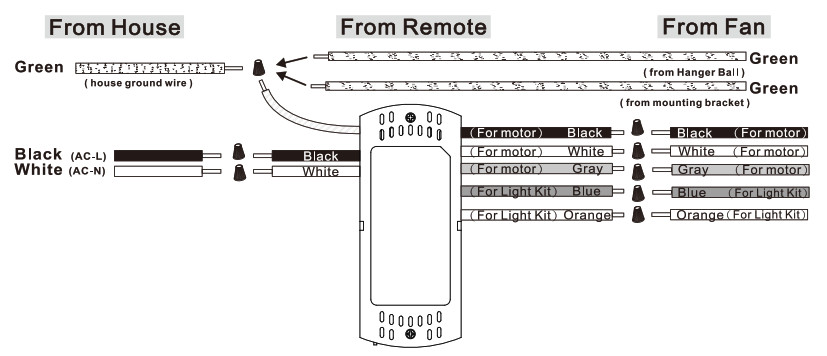
REMOTE PAIRING PROCESS
The Pairing Process is only necessary when there is an issue. Remote set is pre-paired from the factory and should not require the Pairing Process.A fan may need to have “Pairing Process” performed for the following issues.1. Replacing the transmitter.2. Replacing the receiver.3. Multiple fans on the same circuit.(In multiple fans situation, each fan must be wired up individually for the Pairing Process; see step 9-1.)9-1. Pairing Process for transmitter and receiver:1. Switch off the main power ![]() and make sure fan has completely stopped .2. Install a New receiver or install the battery in a new transmitter before the Pairing Process.3. Switch on the power again, and immediately:
and make sure fan has completely stopped .2. Install a New receiver or install the battery in a new transmitter before the Pairing Process.3. Switch on the power again, and immediately: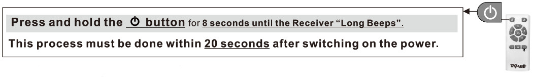 This fan has completed the pairing successfully and the fan is ready for operation!9-2A. Pairing Process for Multiple fans (One transmitter for multiple receivers)If you wish to use only one transmitter for two fans, simply wire up both fans at one time and perform the Pairing Process at step 9-1 from a point between the two fans.

9-2B. Pairing Process for Multiple fans (One transmitter for one receiver)The Pairing Process must be performed on each remote set (transmitter and receiver) individually. See the set up at step 9-3.9-3. TOSET UP REMOTE FOR #1 FANMake sure to turn off power at breaker box. ![]() Disconnecting wire from #2 fan.Before starting the remote control setting process, lower the canopy of #2 Fan and disconnect the Black wire. Put the wire nut on the black wire from the house
Disconnecting wire from #2 fan.Before starting the remote control setting process, lower the canopy of #2 Fan and disconnect the Black wire. Put the wire nut on the black wire from the house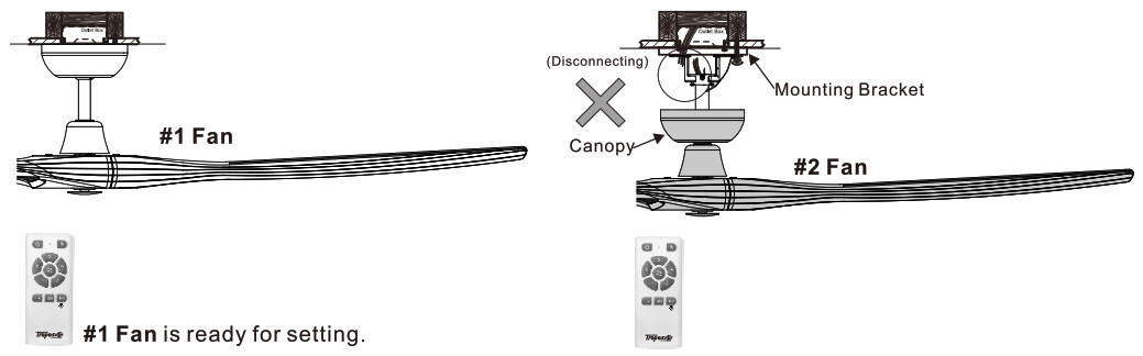 Turn on power at breaker box and #1 Fan is ready for pairing.
 ![]() *See the remote control setting process 9-1 to set up #1 Fan.
*See the remote control setting process 9-1 to set up #1 Fan.
9-4 TO SET UP REMOTE FOR #2 FAN
Make sure to turn off power at breaker box. ![]() Disconnection wire from #1 FanDisconnect the Black wires from #1 Fans and connect the Black wires back to #2 Fan that you remove from 9-3.
Disconnection wire from #1 FanDisconnect the Black wires from #1 Fans and connect the Black wires back to #2 Fan that you remove from 9-3.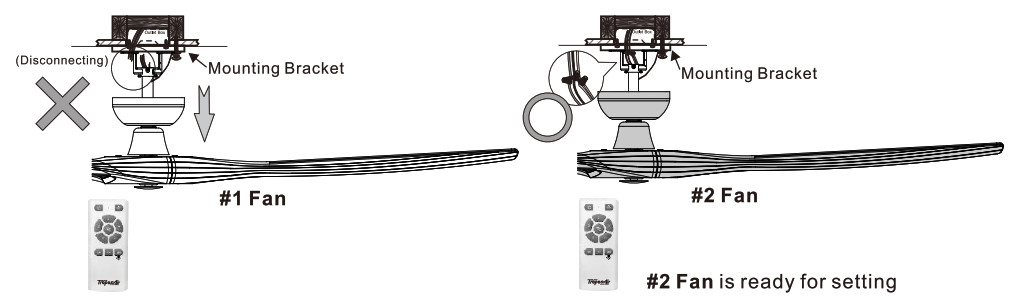
Turn on power at breaker box and #2 Fan is ready for setting. ![]() *See the remote control setting process for 9-1 to set up #2 Fan.
*See the remote control setting process for 9-1 to set up #2 Fan.
9-5. RECONNECT ALL FANSMake sure to turn off power at breaker box.![]() After all the fans have done the resetting process, reconnect all the wires for #1 fan & #2 fan, and lift up the Canopy of #1 fan & #2 fan.
After all the fans have done the resetting process, reconnect all the wires for #1 fan & #2 fan, and lift up the Canopy of #1 fan & #2 fan. 9-6. Switch on the main power and now each of these two fans are operated by its own remote individually.
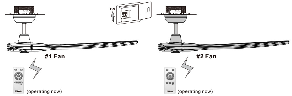 NOTE: For more than two fans, the same rules apply. Make sure only one fan at a time is connected to power when doing the Remote Setting. Already completed fans should be disconnected until all fans have completed the Remote Setting process.
WIFI PAIRING
A. InstallationYou can scan the QR code below to download the Smart Life app. You can also search “Smart Life” in major application markets to install the app. https://smartapp.tuya.com/smartlife
B. Register an account and log in. C. WiFi Connect
NOTE: You must turn on the ”Location Services” before WiFi pairing.1. First ensure that WiFi can be used normally.2. Click “Add Device”, first select “Small Home Appliance”, then select “Fan”.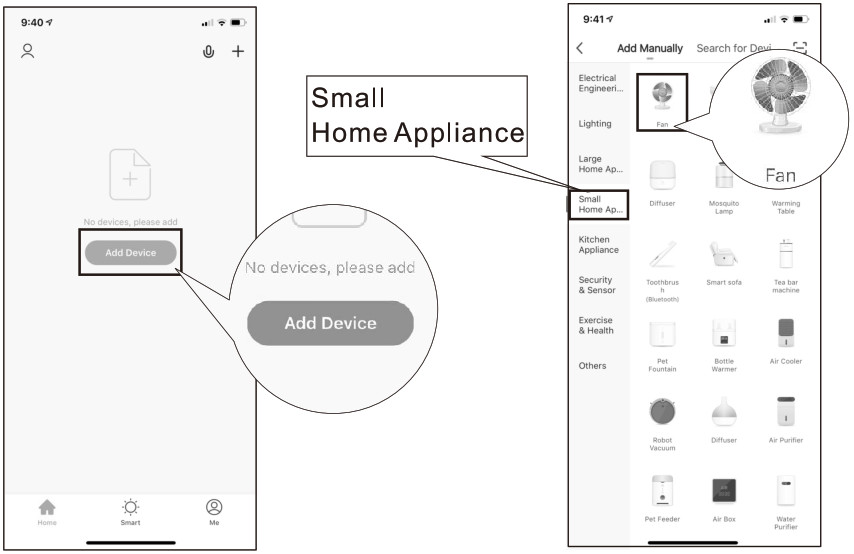 3. Press and hold the “8H” button of the transmitter for more than 5 seconds. Wait until the ceiling fan receiver emits “BeeBee” continuously.
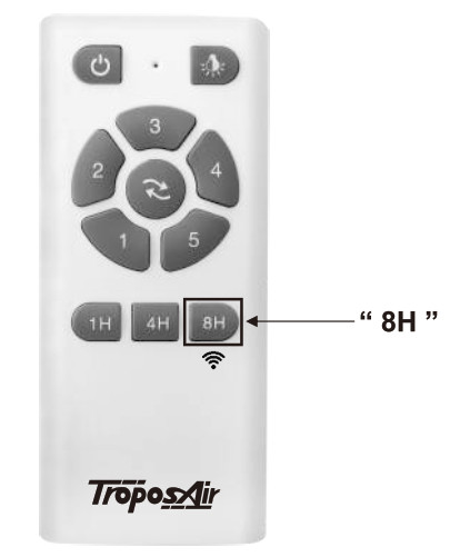
4. Select the correct WiFi source, then enter the WiFi password and click “Confirm” to wait while “connecting”.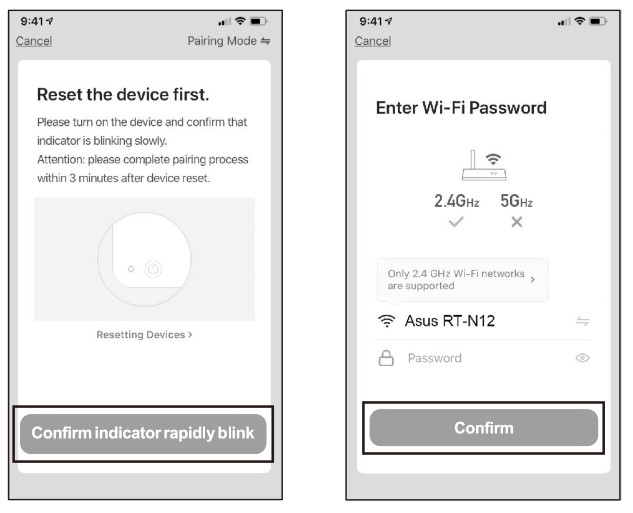 5. Wait for a successful connection.
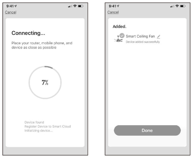 NOTE: If WiFi Pairing failed, please follow below instruction.1. Press and hold the “4H” button of the transmitter for more than 5 seconds. Wait until the ceiling fan receiver emits “BeeBee” continuously.
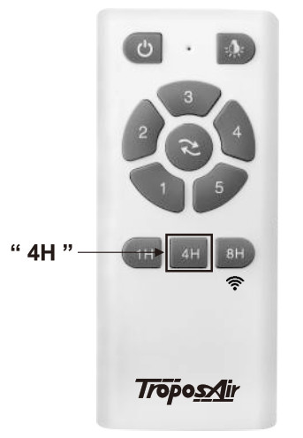 2. Select Pairing Mode “AP Mode” on mobile device.
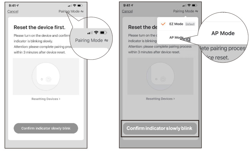 3. Select the correct WiFi source, then enter the WiFi password and click “Confirm” to wait while “Connecting”.
 4. Wait for a successful connection.
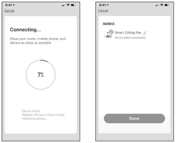 D. Multiple Users1. In the App’s Main Control Panel, click the “
![]() ” in the upper right corner for more functions.2. Click “Share Device”, “Add Sharing”.
” in the upper right corner for more functions.2. Click “Share Device”, “Add Sharing”.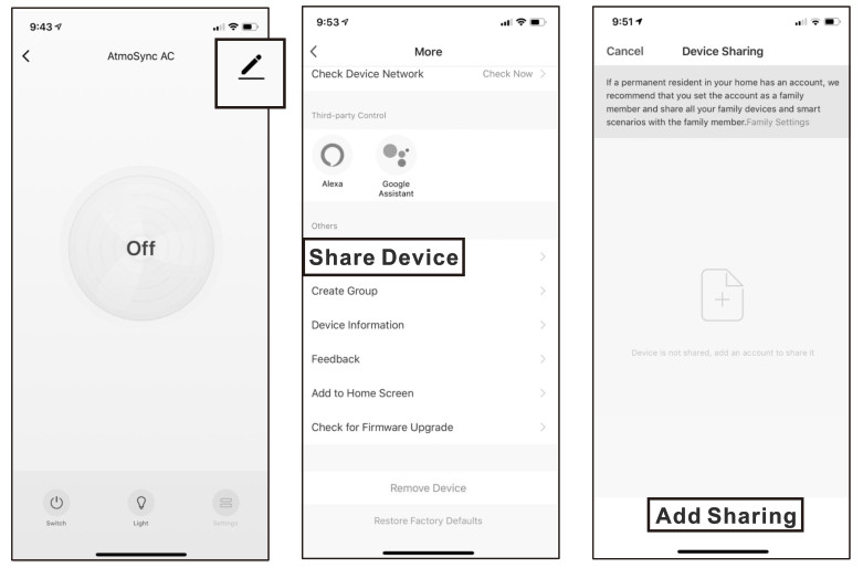 3. Enter the phone number of another Smart Life user, and click “Completed” to share. Hint: The simplest way to share multiple devices with multiple users is to log in as a public account,
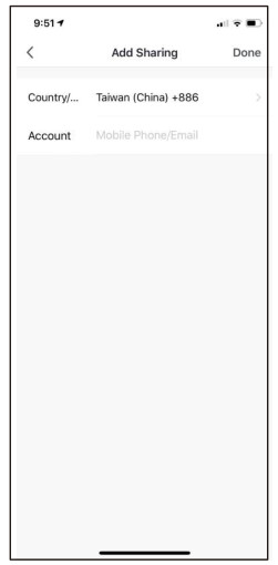 NOTE: This method requires the other users have the “Smart Life” app installed.E. For more information, go to the “Me” – “FAQ & Feedback” in the app to learn.
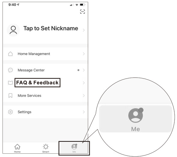
[xyz-ips snippet=”download-snippet”]