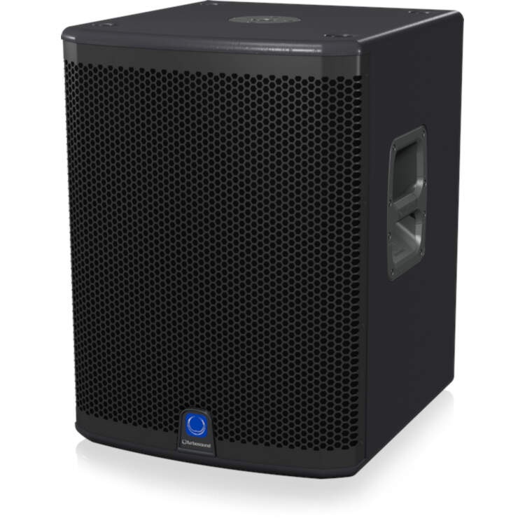
Turbosound Powered Loudspeaker 3000 Watt
Unpacking the Loudspeaker
After unpacking the unit please check carefully for damage. If damage is found, please notify your supplier at once. You, the consignee, must instigate any claim. Please retain all packaging in case of future re-shipment.
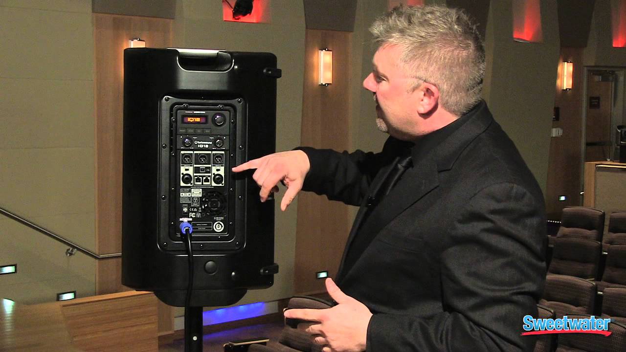
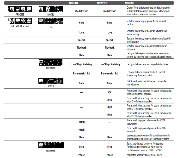
Controls

- LCD SCREEN displays the current DSP module and parameter settings.
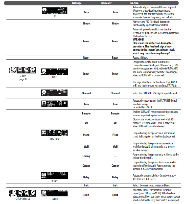
- SETUP button steps through parameters within DSP processing modules.
- PROCESS button steps through the DSP processing modules.
- SIGNAL LED lights up to indicate the channel is receiving a signal.
- GAIN controls adjusts the analogue input level. To increase signal gain, rotate the controls clockwise; to reduce the gain, rotate the knobs counter-clockwise. (Fullrange models have separate GAIN knobs for channels A and B, while iQ15B and iQ18B subwoofers have a single dedicated A/B knob for both channels.)
- OUTPUT A/OUTPUT B XLR connectors provide un-processed copies of the INPUT A or INPUT B signals.
- LINE/MIC switch adjusts the input sensitivity for INPUT A and INPUT B.
- INPUT A/INPUT B combo jacks accept input signals using XLR, balanced ¼” TRS or unbalanced ¼” TS connectors.
- POWER switch turns the unit on and off .
- AC INPUT accepts power connections from power cables fi tted with Neutrik powerCON twist-locking connectors.
- ENCODER KNOB toggles between Graphic and Edit modes (when pressed) and changes parameter values (when rotated).
- EXIT button returns to the top-level DSP screen when pressed.
- ENTER button saves changes and deactivates Edit mode when pressed.
- MIX OUTPUT XLR jack (unavailable on iQ15B and iQ18B subwoofers) sends out a post-GAIN signal composed of the summed INPUT A and INPUT B signals.
- USB connection enables fi rmware updates and remote control over parameters via computer. Please visit turbosound.com to download DSP control software for your computer.
- ULTRANET THRU sends out unprocessed digital audio from the ULTRANET IN connector to additional ULTRANET-equipped devices.
- ULTRANET IN RJ45 plug comes with 2 linked green status LEDs. Whenever a CAT5 cable has been connected, and a valid ULTRANET signal is detected, both LEDswill light up simultaneously to indicate that the ULTRANET signal is ready to use.
- VENTILATION FAN speed adjusts automatically to ensure trouble-free operation.
- AC LINK OUTPUT connects power to other devices using power cables with Neutrik powerCON twist-locking connectors.
Networking capability
All iQ powered loudspeakers off er remote control via USB. The USB connection allows the user to confi gure and monitor all DSP parameters using dedicated iQ software for PC.The DSP fi rmware can also be updated via the USB connection. Visit turbosound.com for the latest fi rmware version. iQ speakers also off er proprietary ULTRANET networking capabilities through the ULTRANET IN and THRU connections using CAT5 cables with RJ45 connectors. ULTRANET allows the user to transmit unidirectionally up to 16 independent channels of 24-bit audio throughout the iQ system, as well as other ULTRANET-equipped devices such as digital mixers and personal monitor systems. Up to 7 devices can be connected in series on a single ULTRANET cable. ULTRANET can also be used for remote control of the iQ selection of modeled speakers.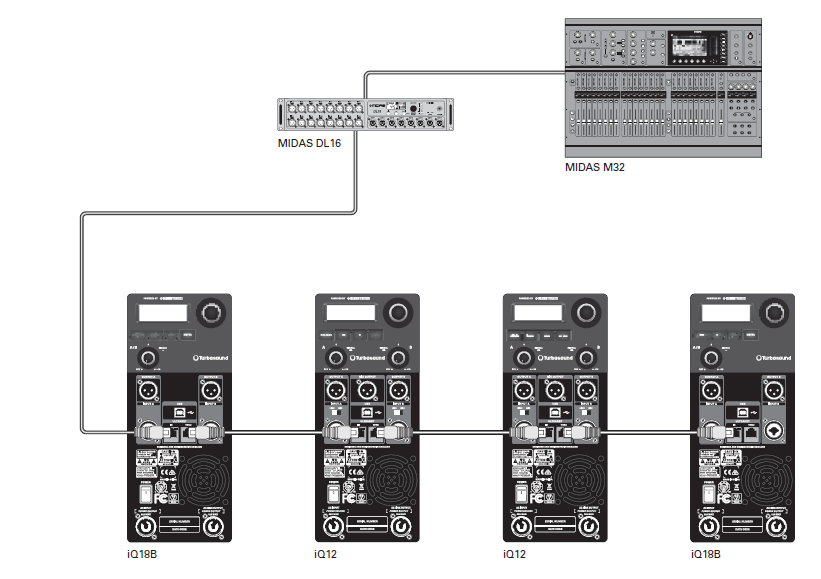
Networked mains power
iQ loudspeakers also facilitate networked transmission of mains power using power cables with Neutrik power CON locking power connectors. To set up networked mains power between iQ loudspeakers, fi rst run a power cable terminating in a powerCON connector to the AC INPUT connector on the rear panel. To power additional bspeakers downline, run power cables equipped with power CON connectors at both ends from the fi rst speaker’s AC LINK OUTPUT to the AC INPUT of the next iQ bloudspeaker in series. The maximum number of linked systems depends on the AC supply voltage as well as the maximum current draw of the individual systems in the power chain. When linking a power chain, make sure that the integrated connectors as well as the supplied AC mains cable are never overloaded. If you are uncertain how to calculate the total current draw, please contact your dealer.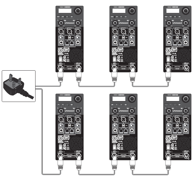
LCD Graphic Indicators
 LCD Graphic Indicators
To help the user immediately recognize that a parameter has been selected and changed from the initial default setting, the parameter’s related text on the top-level screen will invert and change to black text on a white background. As an example, the following screenshots show how the text for the MODEL function changes when the iQ8 default sound has been changed to the modeled PS8 sound: This indicator function occurs only on the main DSP menu level and works for all DSP-related functions, except for the LOAD, SAVE and SETUP sub-sections on the second page of the top-level SETUP menu.
Mounting and fixing
iQ series powered loudspeakers are designed with multiple internal rigging points to suit many possible mounting methods in permanent installations. All cabinets can be simply suspended using optional M10 eyebolts coupled to the internal rigging points provided on the top, bottom, sides and back. The simplest method is to use the two rigging points on the top and a single pull-back rigging point in the centre of the rear panel. Remove the appropriate plastic caps and insert eyebolts, which must have a thread length of at least 30 mm. Use the rear rigging point to angle the cabinet for optimum room coverage.
Wall and Ceiling Brackets
TURBOSOUND iQ8-WB, iQ10-WB, iQ12-WB and iQ15-WB wall and ceiling brackets are optionally available for iQ series. The graphic below shows the assembly of the optional mounting brackets (iQ8-WB, iQ10-WB, iQ12-WB and iQ15-WB).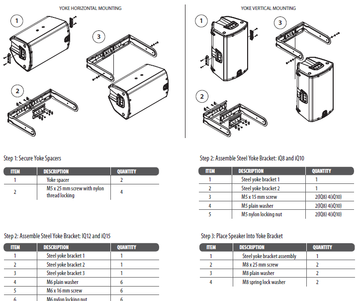
NOTE: For iQ8 and iQ10, the fi nished bracket requires only 2 pieces, while the iQ12 and iQ15 bracket requires 3 pieces.
Pole Mounting
Fullrange iQ loudspeaker models (iQ8, iQ10, iQ12 and iQ15) may also be pole mounted, either independently or in conjunction with iQ subwoofer models (iQ15B, iQ18B).The iQ pole mount sockets allow fullrange models to be mounted straight or angled 7.5° downwards for optimum coverage. iQ10, iQ12 and iQ15 models may also be placed on one side and deployed as wedge monitors. These models have been designed with sides angled at 48° to help with upward sound dispersion.
Transport
The subwoofers are supplied with castors for ease of transportation when used as a portable sound system. To assemble the castors to the back of the cabinets, remove the 16 bolts from the rear of the speaker, align the castors with the mount holes and replace the bolts.IMPORTANT NOTE: The mounting of a permanently installed sound system may be dangerous unless undertaken by qualified personnel with the required experience and certification to perform the necessary tasks. Walls, floors or ceilings must be capable of safely and securely supporting the actual load. The mounting accessory used must be safely and securely fixed both to the loudspeaker and to the wall, floor or ceiling. When mounting rigging components on walls, floors or ceilings, ensure that all fixings and fasteners used are of an appropriate size and load rating. Wall and ceiling claddings, and the construction and composition of walls and ceilings, all need to be taken into account when determining whether a particular fixing arrangement can be safely employed for a particular load. Cavity plugs or other specialist fixings, if required, must be of an appropriate type, and must be fitted and used in accordance with the maker’s instructions. The operation of your speaker cabinet as part of a flown system, if installed incorrectly and improperly, can potentially expose persons to serious health risks and even death. In addition, please ensure that electrical, mechanical and acoustic considerations are discussed with qualified and certified (by local state or national authorities) personnel prior to any installation or flying. Make sure that speaker cabinets are set up and flown by qualified and certified personnel only, using dedicated equipment and original parts and components delivered with the unit. If any parts or components are missing please contact your Dealer before attempting to set up the system. Be sure to observe the local, state and other safety regulations applicable in your country. MUSIC Group, including the MUSIC Group companies listed on the enclosed “Service Information Sheet”, assumes no liability for any damage or personal injury resulting from improper use, installation or operation of the product. Regular checks must be conducted by qualified personnel to ensure that the system remains in a secure and stable condition. Make sure that, where the speaker is flown, the area underneath the speaker is free of human traffic. Do not fly the speaker in areas that can be entered or used by members of the public. Speakers create a magnetic field, even if not in operation. Therefore, please keep all materials that can be affected by such fields (discs, computers, monitors, etc) at a safe distance. A safe distance is usually between 1 and 2 meters.
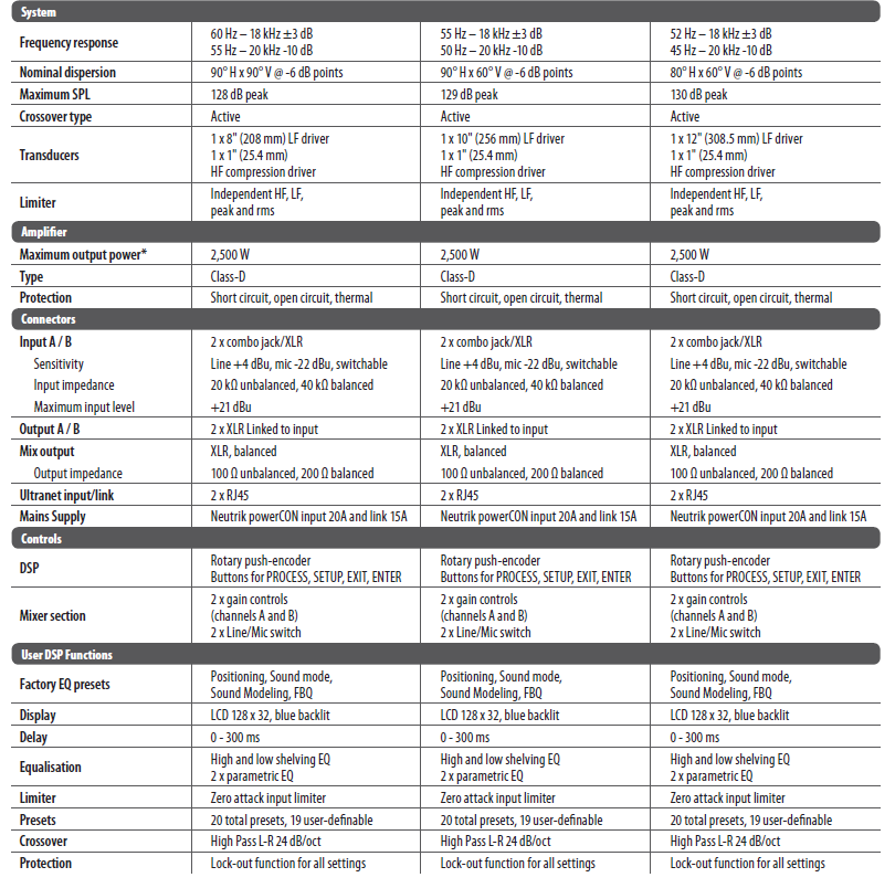
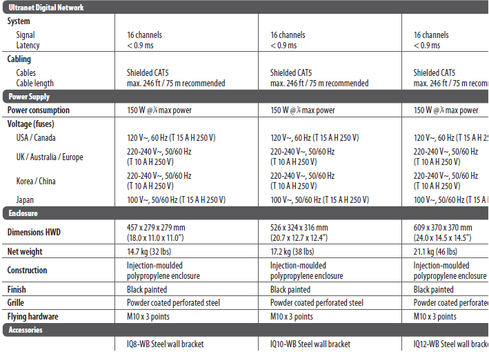
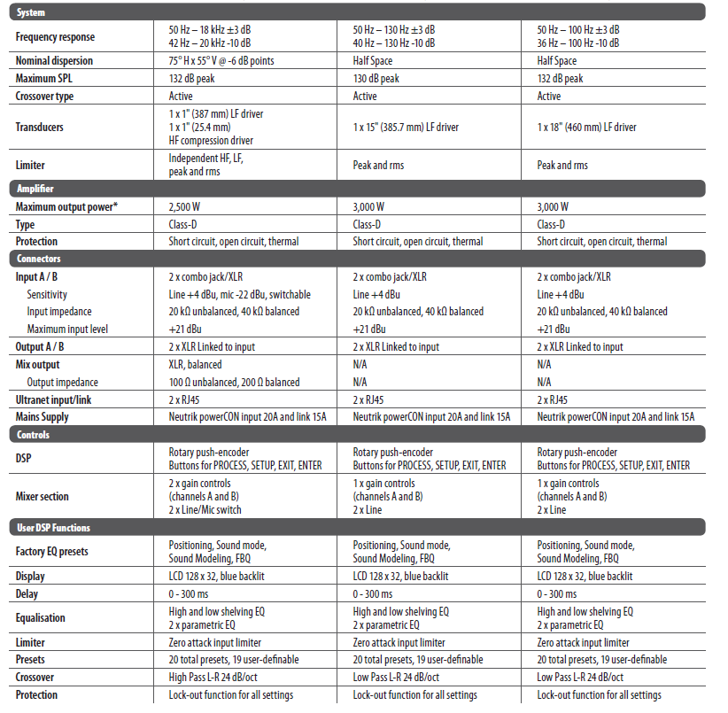
Technical Specifications

Other important information
Important information
- Register online. Please register your new Music Tribe equipment right after you purchase it by visiting turbosound.com. Registering your purchase using our simple online form helps us to process your repair claims more quickly and effi ciently. Also, read the terms and conditions of our warranty, if applicable.
- Malfunction. Should your Music Tribe Authorized Reseller not be located in your vicinity, you may contact the Music Tribe Authorized Fulfi ller for your country listed under “Support” at turbosound.com. Should your country not be listed, please check if your problem can be dealt with by our “Online Support” which may also be found under “Support” at turbosound.com. Alternatively, please submit an online warranty claim at turbosound.com BEFORE returning the product.
- Power Connections. Before plugging the unit into a power socket, please make sure you are using the correct mains voltage for your particular model. Faulty fuses must be replaced with fuses of the same type and rating without exception.
![]()
FEDERAL COMMUNICATIONS COMMISSION COMPLIANCE INFORMATIONResponsible Party Name: Music Tribe Brands UK Ltd.Address: Klark Industrial Park, Walter Nash Road, Kidderminster, Worcestershire, DY11 7HJ United KingdomPhone Number: +44 1562 732290
References
[xyz-ips snippet=”download-snippet”]