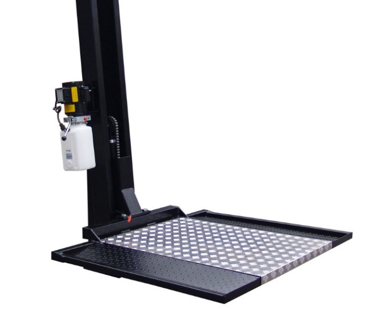
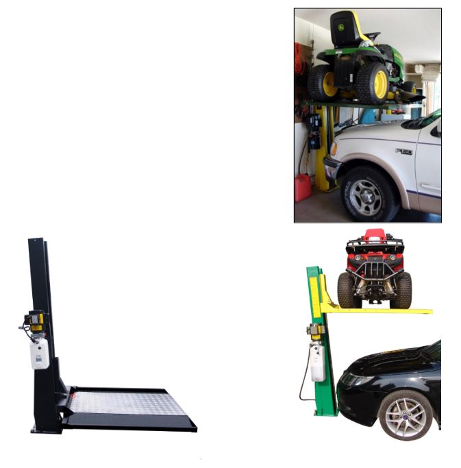
Single Column Platform Storage Lift
SC-2K User Manual

PREFACE
Prior to the operation of your lift make sure that you have read the instructions thoroughly. Instructions are found in this manual. Please note that your warranty can be voided if you do not read the manual and understand its content. If you have any questions, concerning operation, safety or application of your lift, please consult your distributor.
IMPORTANT NOTES
READ THE INSTALLATION AND OPERATION MANUAL IN ITS ENTIRETY BEFORE ATTEMPTING TO INSTALL THE LIFT.
- Do not install this lift on any surface other than concrete, conforming to minimum specifications.
- Do not install this lift over expansion joints or cracks. Check with building architect.
- Do not install this lift on a second floor with a basement beneath without written authorization from building architect.
- Do not install this lift outdoors unless special consideration has been made to protect the power unit from inclement weather conditions.
- A level floor is recommended for proper installation and operation. Concrete should be a minimum of 4-1/4” thickness and 3,000 psi tensile strength with steal or fiber mesh reinforcement.
- The lift is intended to raise the entire body of the vehicle. Do not attempt to lift only part of the vehicle. Improper use of this equipment could result in damage to the lift, yourself or other property.
- The lift is intended to lift vehicles only. It is not designed to lift any person or equipment containing persons.
- Users of this equipment should be qualified, responsible and should follow the operation and safety guidelines set forth in this manual.
- For specifications on concrete pads, please call for technical assistance.
- Improper installation can cause damage or injury. The Manufacturer will NOT assume liability for loss or damage of any kind, expressed or implied, resulting from improper installation or use of this product.
DEFINITION
Surface Mounted, Single-Post Lift w/ Hydraulic ‘chain-over’ Drive, 2,000 lbs. capacity.The name / model number is designated below:
- Model Number: SC-2K – Single Column Platform Storage Lift(Note: Removable Aluminum Decking is not designed to be load bearing)
SITE PREPARATION
Make sure you have made all necessary measurements to assure that your lift will fit in your shop / garage and accommodate the type of vehicle you intend to lift with it. Make sure you have enough clearance at the top, and enough width to allow walking around. Also, be aware that the electrical power supply requirements are 115 volt, 1 Phase, 20 amps.
REQUIRED TOOLS
The installation of this lift is relatively simple and can typically be accomplished by 2 men in a few hours. The following tools and equipment are needed or recommended.
- Fork Lift and/or Engine Hoist for moving pieces & positioning lift column, is recommended. (You will also need a ten-foot length of 3/8” chain.)
- Rotary Hammer Drill with 3/4” Masonry Drill Bit. (Core Drill Rebar Cutter recommended)
- 6 quarts of Non-Detergent / Non-Foaming Hydraulic Oil – SAE-10, AW 32 or equivalent
- 1” and 5/16” Wrench & Socket with Ratchet
- 1” and 1/8” Socket & Extension
- 1/2” Wrench
- 11/16” Wrench
- Adjustable Wrench
- Small Crowbar or large Screwdriver for aligning bolt holes
- Pliers
- Flat Blade Screwdriver
- Tin Snips
- Gloves
GENERAL INFORMATION
- Carefully remove the crating and packing materials.CAUTION! Be careful when cutting steel banding material as items may become loose and fall causing personal harm or injury.
- Identify the components and check for damage or shortages.Please contact your distributor immediately, if any damages or shortages are discovered.
PACKAGING
- The SC-2K lift assembly is packaged & shipped as two large pieces – Column & Platform assemblies.
- The SC-2K column comes with cylinder, carriage & chain with the hardware box located inside the column.
- The SC-2K platform comes with frame and aluminum decking.
- The electric-hydraulic power unit is packaged separately and banded to top of platform.
FOUNDATION and ANCHORING REQUIREMENTS
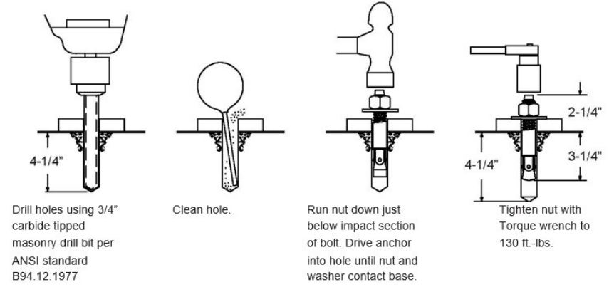
- Concrete shall have compression strength of at least 3,000 PSI and a minimum thickness of 4-1 /4″ in order to achieve a minimum anchor embedment of 3-1/4″. NOTE: When using the standard supplied 3/4″ x 5-1/2″ long anchors, if the top of the anchor exceeds 2-1/4″ above the floor grade, you DO NOT have enough embedment.
- Maintain a 6″ minimum distance from any slab edge or seam. Hole to hole spacing should be a minimum 6-1 /2″ in any direction. Hole depth should be a minimum of4-1/4″.
- DO NOT install on asphalt or other similar unstable surface. Columns are supported only by anchoring to floor.
- Using the horseshoe shims provided, shim each column base as required until each column is plumb. If one column has to be elevated to match the plane of the other column, full size base shim plates should be used. Torque anchors to 130 ft- lbs. Shim thickness MUST NOT exceed 1/2″ when using the 5-1/2″ long anchors provided wi1h the lift.
- If anchors do not tighten to 130 ft-lbs. installation torque, replace the concrete under each column base with a 4′ x 4′ x 6″ thick 3 000 PSI minimum concrete pad keyed under and flush with the top of existing floor. Allow concrete to cure before installing lifts and anchors (typically 2 to 3 weeks).
ANCHORING TIPS
- Use a concrete hammer drill with a carbide tip, solid drill bit the same diameter as the anchor, 3/4″ – (.775 to .787 inches diameter). Do not use excessively worn bits or bits which have been incorrectly sharpened.
- Keep the dri ll in a perpendicular line while drilling.
- Let the drill do the work. Do not apply excessive pressure. Lift the drill up and down occasionally to remove residue to reduce binding.
- Drill the hole to depth of 2• deeper than the length of anchor. NOTE: Drilling thru concrete (recommended) will allow the anchor to be driven thru the bottom of foundation if the threads are damaged or if the lift will need to be relocated.
- For better holding power blow dust from the hole.
- Place a flat washer and hex nut over threaded end of anchor, leaving the nut almost flush with the top of the anchor bolt. Carefully tap anchor into hole. Do not damage threads. Tap anchor into the concrete until nut and flat washer are against base plate. Do not use an impact wrench to tighten! Tighten the nut, two or three turns on average after the concrete has cured (28-<lay cure). If the concrete is very hard only one or two turns may be required.
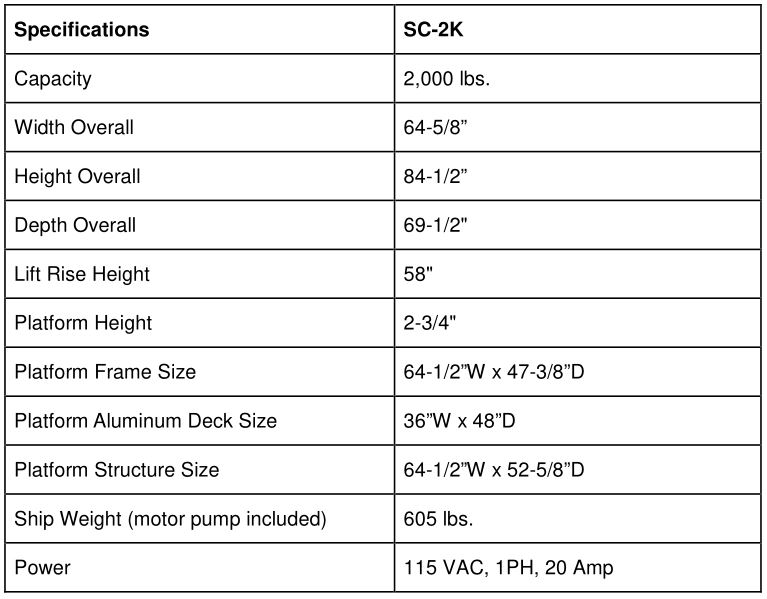
SPECIFICATIONS
IMPORTANT!RECEIVING & HANDLING
- Unloading the LiftIt’s recommended to use a forklift that can handle about 2,000 to 2,500 pounds and operates on a smooth surface.
- Un-banding the LiftThe steel bands which secure the lift parts to the pallets are heavy duty. You’ll need a pair of metal shears or tin snips to cut the bands. Be very careful when doing this because the bands will tend to fly apart when they are cut, and the heavy lift parts may shift when freed from the bands. Stand to the side of the bands when you cut them, and use gloves when removing the cut bands because they have sharp edges.
- Moving Lift ComponentsYou can move the larger components pieces to the garage or service bay with the forklift. Some of the smaller pieces can be moved by two or more people by carrying them. If you have several people helping, some of the larger pieces can be moved manually.
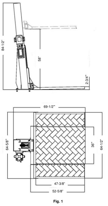
DIMENSIONS
INSTALLATION
(Ensure to Read the Operating Instructions before Operating Lift)
Make sure you have someone to assist with installation as most of the lift components are big, heavy, and cumbersome. The lift column alone weighs about 330 lbs. by itself. The platform frame & aluminum decking weighs around 200 lbs. together.
It is possible for two people to install this lift if they have the appropriate lifting and handling equipment, but it is definitely easier and faster if there are several people available to help maneuver the heavy components into place. As with any assembly involving big heavy materials, safety considerations are a must. Though this lift is more difficult to install than some other Lifts due to the single post design, once installed the lift design & features makes it extremely effective for residential garages, shops and storage facilities.
DESCRIPTION OF THE LIFTING SYSTEM COMPONENTS
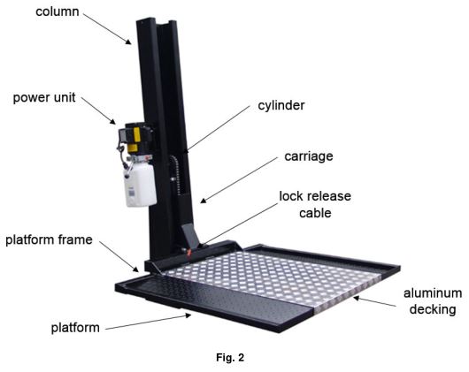
IMPORTANTThe major piece of the lift is the column assembly. It consists of the carriage, hydraulic cylinder, chain hydraulic hose and safety latch release cable already pre-assembled. The column assembly will have a bracket on the side, which will be used for installing the power unit later. The cylinder in the column may appear to be loose in the column, this is normal. After installation, when the platform is raised under power, the cylinder should stabilize itself in an upright plumb position.
STEP 1Carefully remove the shipping brackets. There is one bracket bolted to the underside of the column (Figs. 3, 4, 5) and another bracket bolted to the side of the column (Figs. 6, 7, 8).
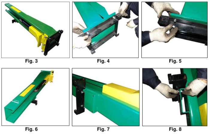
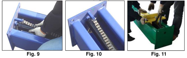
NOTE: If the base of the cylinder is not properly located in the center hole of the column’s baseplate, it will be required to position it into the base plate hole before lifting the column upright (Figs.9 & 10). If required, ensure to slide the carriage to base of the column, while pulling the lock-release cable at the same time (Fig.11).
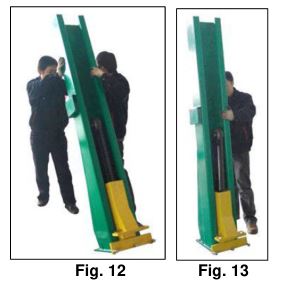
STEP 2Using two people, carefully stand the column upright and maneuver to the predetermined location (Figs.12 & 13).
STEP 3Before proceeding, double check measurements and make certain that the base of the column is properly aligned and in the desired location before anchoring column to floor.
- Using the base plate on the column as a guide, drill each anchor hole into concrete using a rotary hammer drill and 3/4” concrete drill-bit. To assure full holding power, do not ream the hole or allow the drill to wobble. (See Anchoring Details on Page 4)
- After drilling, remove dust thoroughly from each hole using compressed air and/or wire brush.
- Assemble the washers and nuts on anchors then tap into each hole with a block of wood or rubber hammer until the washer rests against the base plate. If shimming is required, ensure that enough threads are left exposed to properly tighten.
- Using a level, check that the column is plumb (sides only). If shimming is required, use supplied Shim stock or 3/4” washers, placing shims as close as possible to the anchor holes locations. This will prevent potential bending for the column base.
- With the shims and anchor bolts in place, tighten by securing the nut to the base then turning 2-3 full turns clockwise. Ensure anchor bolts are tightened to a minimum of 130 ft-lbs. of torque. DO NOT use an impact wrench for this procedure.
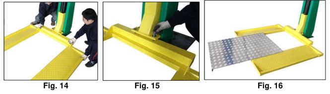
STEP 4Remove Aluminum Decking & secure Platform Frame to Carriage using M20 Bolts, Washers & Nuts. Once Platform is mounted, place Aluminum Decking back on the Platform (Figs. 14, 15 & 16).
STEP 5
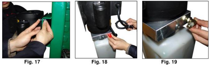
- Attach the power unit to the mount bracket on the side of the Column using the M8 Bolts, Washer and Lock Nuts supplied with Power Unit (Fig.17).
- Remove the red plug from valve body and install the Elbow Fitting (Figs. 18 & 19).

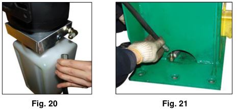
- Connect one end of the Hydraulic Hose to the Elbow Fitting installed on Power Unit (Fig. 20).
- Connect the other end of Hydraulic Hose to the cylinder fitting located on the lower backside of Column (Fig.21).NOTE: Ensure all hydraulic connections are properly tightened. Do Not Over Tighten.
- Remove black vent cap from power unit’s reservoir and fill with hydraulic oil. Make sure the funnel used to fill the power unit is clean. Ensure Not to Fill Above Max Fill Line.NOTE: Use Non-Detergent / Non-Foaming Hydraulic Oil – SAE-10, AW 32 or equivalent. The Power Unit’s reservoir holds approximately 6 quarts of fluid.
- (Optional) Secure Hydraulic Hose to Column using Hose Clamps & M4 Screws.
STEP 6Connect the power unit’s cord with plug w/ grounding pin to electrical 110-115VAC power source. If an extension cord is required, ensure the proper gauge extension cord is used. If there is any question on the power source requirements, please consult an electrician.
STEP 7Recheck all bolts for tightness. Installation is now complete.
The SC-2K Lift is now ready for Operation
OPERATING INSTRUCTIONS
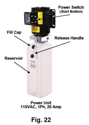
To Raise, push the power switch button on the power unit and hold while it the electric motor turns on. The motor operates an internal pump that forces hydraulic oil into the lift piston, which extends the piston rod & roller chain to raise the lift (Fig 22).
As the lift rises, an internal safety latch will pass over the steel latch stops (rectangular blocks which protrude from the back, inside of the lift column), and you will hear “clanks” as it does so. This sound is normal, and indicates that the safety latch is passing over the latch stops properly. The lift is raised to the desired height by holding the switch button in while it is rising, and releasing the button when the lift has reached its desired position.
For safety, it is required to release the hydraulic pressure inside the cylinder to lower the lift to nearest lower latch stop. To do this, simply press down the release handle on the power unit. Then, the lifting frame and carriage’s safety latch will rest on the latch stop inside the column (Fig 22).
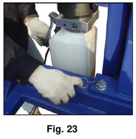
To Lower, first you need to depress the power switch button a second or two to raise the lift up a little. Then, pull the safety latch release cable to disengage the safety latch to fully lower. After that press down the release handle again and hold (Fig. 23).
The weight of the vehicle will cause the lift to lower by gravity. No power is required to be applied to the power unit while lowering, but the safety latch must be disengaged to allow the lift to lower past the latch stops.
After the installation is complete, raise the lift about two feet high and then fully lower. Repeat this process two or three times and check reservoir fluid level, while fully lowered. Only add hydraulic fluid to the reservoir’s fill line, if necessary. This assures that hydraulic oil is properly distributed throughout the hydraulic system.
NOTE: Only add hydraulic fluid to the reservoir with the lift in the fully “down” position. If you fill the reservoir in the “up” position and then lower the lift, there will be too much hydraulic oil in the system, and will possibly squirt out of the reservoir tank.
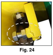
Platform Adjustment:To adjust the Platform levelness, adjust the 3ea bolts & nuts on the underside of the Platform Frame (Fig. 24).
RAISING A VEHICLE
With Lift in the fully lowered position, carefully drive or push vehicle (Lawnmower or ATV) onto Platform until relatively centered. Then, set parking brake.
NOTE: Ensure wheels are positioned on the Platform Frame only. Aluminum Decking is not designed to be load bearing.
Depress the “up” button and the vehicle will rise. Raise the vehicle until it is near the ceiling of the garage.
BE CAREFUL NOT TO RAISE THE VEHICLE SO HIGH THAT IT STRIKES THE CEILING! BE AWARE OF ANYTHING THAT PROTRUDES FROM THE CEILING, LIKE LIGHTBULBS, GARAGE DOOR OPENERS OR DOOR TRACKS. IT IS VERY HELPFUL IF YOU HAVE A SPOTTER ON A LADDER TO TELL YOU WHEN YOU ARE NEAR THE CEILING FOR THE FIRST LIFT!
When the vehicle is in the correct position, it is useful to mark the position of the carriage relative to the column with two pieces of electrical tape or a felt tip marker. When you make future lifts, all you have to do is operate the lift till the reference marks line up, and you will know that the vehicle is in the right position. If you alternate vehicles that you will lift, you will need a separate set of reference marks for each. The higher you lift the raised vehicle, the more headroom you will have to enter and exit the one you park underneath.
MISCELLANEOUS
It may be useful to spray paint the ends of the Platform with a bright fluorescent color to help catch your eye and avoid head bumps, while the lift is in the raised position.
The hydraulic oil should be replaced every two years, and the inside corners of the lift leg should be re-greased with a general-purpose axle grease every year, or as it becomes apparent that it needs it.
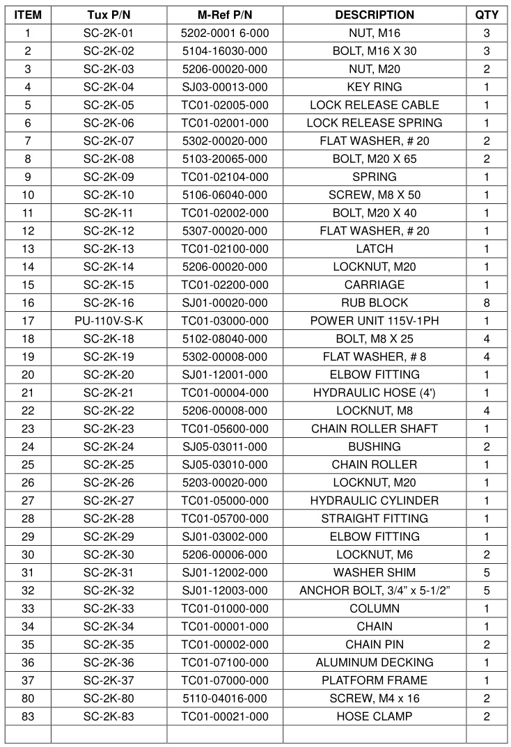
EXPLODED VIEW
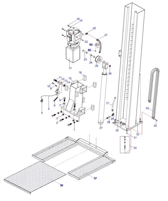
PARTS LIST
POWER UNIT PRIMING
WARNING!! Failure to properly relieve pressure in the following steps can cause injury to personnel.
IMPORTANTPOWER UNIT PRIMING PROCEDURE
THE PROBLEM· Power unit runs fine but will not pump any fluid.
Step 1 – Locate the check: valve. It’s the flush plug to the eft of the lowering valve.
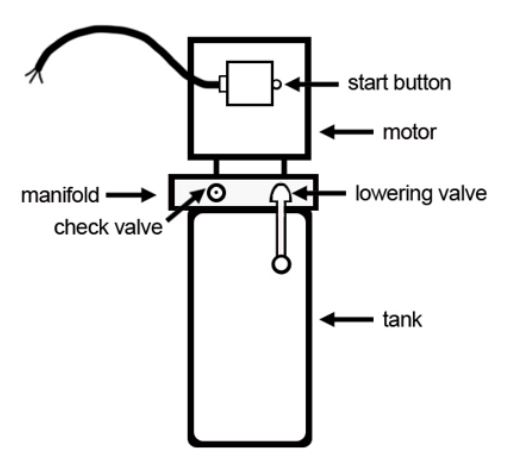
Step 2 – Using a Hex wrench and shop towel -with shop towel in place to catch fluid loosen the chock valve plug by approximately 2-½ turns and allow fluid to bleeds off.
Step 3 – Push the START button for one second, then release for three seconds. Repeat these steps until unit starts pumping fluid.
Step 4 – Tighten the check valve plug.
YOUIR POWER UNIT SHOULD NOW IBE PRIMED
LIMITED WARRANTY
Structural Warranty:The following parts and structural components carry a five year warranty:ColumnsArmsUprightsSwivel PinsLegsCarriagesOverhead BeamTracksCross RailsTop Rail Beam
Limited One-Year Warranty:
Tuxedo Distributors, LLC offers a limited one-year warranty to the original purchaser of Lifts and Wheel Service equipment in the United States and Canada. Tuxedo will replace, without charge, any part found defective in materials or workmanship under normal use, for a period of one year after purchase. The purchaser is responsible for all shipping charges. This warranty does not apply to equipment that has been improperly installed or altered or that has not been operated or maintained according to specifications.
Other Limitations:
This warranty does not cover:
- Parts needed for normal maintenance
- Wear parts, including but not limited to cables, slider blocks, chains, rubber pads and pulleys
- Replacement of lift and tire changer cylinders after the first 30 days. A seal kit and installation instructions will be sent for repairs thereafter.
- On-site labor
Upon receipt, the customer must visually inspect the equipment for any potential freight damage before signing clear on the shipping receipt. Freight damage is not considered a warranty issue and therefore must be noted for any potential recovery with the shipping company.
The customer is required to notify Tuxedo of any missing parts within 72 hours. Timely notification must be received to be covered under warranty.
Tuxedo will replace any defective part under warranty at no charge as soon as such parts become available from the manufacturer. No guarantee is given as to the immediate availability of replacement parts.
Tuxedo reserves the right to make improvements and/or design changes to its lifts without any obligation to previously sold, assembled or fabricated equipment.
There is no other express warranty on the Tuxedo lifts and this warranty is exclusive of and in lieu of all other warranties, expressed or implied, including all warranties of merchantability and fitness for a particular purpose.
To the fullest extent allowed by law, Tuxedo shall not be liable for loss of use, cost of cover, lost profits, inconvenience, lost time, commercial loss or other incidental or consequential damages.
This Limited Warranty is granted to the original purchaser only and is not transferable or assignable.
Some states do not allow exclusion or limitation of consequential damages or how long an implied warranty lasts, so the above limitations and exclusions may not apply. This warranty gives you specific legal rights and you may have other rights, which may vary from state to state.
1905 N Main St Suite C, Cleburne, TX 76033Ph. 817-558-9337 / Fax 817-558-9740
Single Column Platform Storage Lift SC-2K User Manual – Single Column Platform Storage Lift SC-2K User Manual –
[xyz-ips snippet=”download-snippet”]