Ubiquiti Networks 8-Port PoE-Powered Gigabit Switch with PoE Passthrough Instruction Manual
Introduction
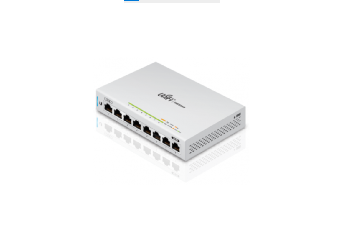
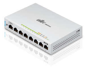
Thank you for purchasing the Ubiquiti Networks® UniFi® 8-Port PoE-Powered Gigabit Switch with PoE Passthrough. This Quick Start Guide is designed to guide you through the installation and also includes the warranty terms.
Package Contents
UniFi Switch
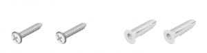
Mounting Screws Screw Anchors(Qty. 2) (Qty. 2)
* Power Adapter and Power Cord are not included with US-8 5-Pac
System Requirements
- Linux, Mac OS X, or Microsoft Windows 7/8/10
- Java Runtime Environment 1.6 (1.8 or newer recommended)
- Web Browser: Google Chrome (Other browsers may have limited functionality)
- UniFi Controller software v5.3.x (or newer), available at:
downloads.ubnt.com/unifi
TERMS OF USE: All Ethernet cabling runs must use CAT5 (or above). It is the customer’s responsibility to follow local country regulations, including operation within legal frequency channels, output power, indoor cabling requirements, and Dynamic Frequency Selection (DFS) requirements.
Network Topology Requirements
• A DHCP-enabled network for the UniFi Switch to obtain an IP address (connected devices will also obtain IP addresses after deployment)• A UniFi Cloud Key or management station running the UniFi Controller software v5.3 (or newer), located either on-site and connected to the same Layer 2 network, or off-site in a cloud or NOC
All UniFi devices support off-site management controllers. For setup details, refer to the User Guide on the website:documentation.ubnt.com/unifi
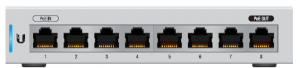
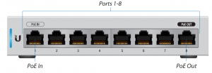
Hardware OverviewFront Panel
| Port | Description |
| Ports 1-8 | RJ45 ports support 10/100/1000 Ethernet
connections. |
| PoE In
(Port 1) |
Supports 802.3af/at or 48V Passive PoE to power the switch and can provide 48V (2-pair) PoE passthrough to port 8. |
| PoE Out
(Port 8) |
PoE output is Off by default. Enabling PoE output requires 24W input power via PoE In or DC input. |
The UniFi Switch may be powered by PoE through the PoE In port or by DC input using a 48V power adapter. PoE can be enabled on the PoE Out port using the UniFiController software. PoE passthrough supports 48V (2-pair).
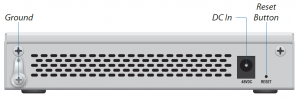
Back Panel
| Port | Description |
| Ground | Ancillary grounding point for enhanced ESD protection. |
| DC In | To power the switch by DC input, connect a 48V
power adapter to the 48VDC port. |
| Reset
Button |
This button serves two functions for the UniFi
Switch: |
| • Restart Press and release the Reset button quickly. | |
| • Restore to Factory Default Settings Press and hold the Reset button for more than five seconds. |
LEDs
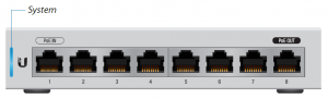
System LED
| State Status | |
| Flashing White | Initializing. |
| Steady White | Factory defaults, waiting for integration. |
| Alternating
White/Blue |
Device is busy; do not touch or unplug it. This usually indicates that a process such as a firmware upgrade is taking place. |
| Steady Blue | Successfully integrated into a network and working properly. |
| Flashing Blue | This is used to locate a device.
When you click Locate in the UniFi Controller software, the System LED will flash blue. The software will also display the location of the UniFi Switch on the map. |
RJ45 LEDs
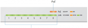
Link/Speed/Activity
| LED | State | Status |
|
PoE |
Off | PoE Disabled |
| Amber | 48V Passive PoE | |
|
Link/ Speed/ Activity |
Off | No Link |
|
Amber |
Link Established at 10/100 Mbps
Flashing Indicates Activity |
|
|
Green |
Link Established at 1 Gbps
Flashing Indicates Activity |
Side Panels
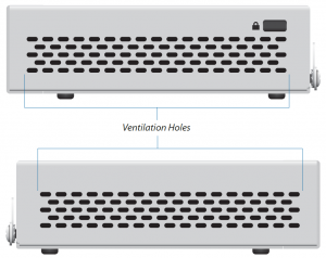
![]() WARNING: FAILURE TO PROVIDE PROPER VENTILATION MAY CAUSE FIRE HAZARD. KEEP AT LEAST 20 MM OF CLEARANCE NEXT TO THE VENTILATION HOLES FOR ADEQUATE AIRFLOW.
WARNING: FAILURE TO PROVIDE PROPER VENTILATION MAY CAUSE FIRE HAZARD. KEEP AT LEAST 20 MM OF CLEARANCE NEXT TO THE VENTILATION HOLES FOR ADEQUATE AIRFLOW.
 WARNING: The US-8 must not be stacked. Do not place it on top of another switch. Do not place anything on top of the US-8
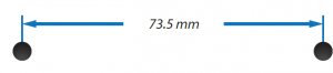
Hardware Installation
The UniFi Switch can be mounted on a vertical surface or placed on a desktop. Follow the Wall Mounting instructions to mount the switch using the included screws and anchors.
WARNING: To reduce the risk of fire or electric shock, do not expose the switch to rain or moisture.
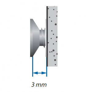
- Drill two 6 mm holes set 73.5 mm apart.
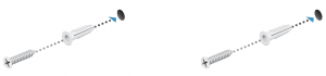
- Insert a Screw Anchor into each hole, and fasten a Screw into each anchor.
- Leave a clearance of approximately 3 mm between the screw head and the wall.
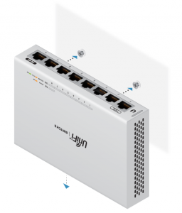
- Mount the UniFi Switch by inserting the screw heads into the mounting slots on the bottom of the switch. Then slide the switch down to lock it in place.
Grounding (Recommended)
The UniFi Switch is grounded through the Power Adapter. When powering the switch with PoE, ground the device by connecting the ancillary ground.
- Loosen the ground screw and secure a ground wire (not included) to the grounding point.
- Secure the other end of the ground wire to a grounding block or other grounded structure.
Connecting PowerThe UniFi Switch can be powered by PoE or DC input using the Power Adapter.
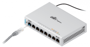
Power by PoEConnect an Ethernet cable from an 802.3af/at or 48V passive PoE power source to the PoE In port.
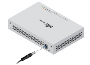
Power by DC Input
- Connect the Power Adapter to the 48VDC port on the back of the UniFi Switch.
- Connect the Power Cord to the Power Adapter. Plug the Power Cord into a power outlet.

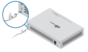
Connecting Ethernet
- Connect an Ethernet cable from your DHCP server or LAN to any port 1 to 7.
- Connect your PoE device to port 8.
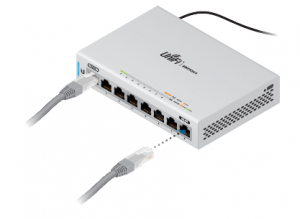
WARNING: Before enabling PoE passthrough in the UniFi Controller, ensure that the connected PoE device supports the PoE power (48V).WARNING: When both PoE In and DC Input are connected, the highest voltage power of the two will immediately pass through to PoE Out.
Software Installation
Download and install the latest version of the UniFi Controller software at downloads.ubnt.com/unifi and follow the on-screen instructions.
 Note: If you already have UniFi Controller v5.3.x or newer installed, skip to the section, Adopting the UniFi Switch. After you have installed the software and run the UniFi Installation Wizard, a login screen will appear for the UniFi Controller management interface. Enter the admin name and password that you created and click Log In.
You can manage your network and view network statistics using the UniFi Controller management interface.To adopt the UniFi Switch, proceed to the Adopting the UniFi Switch section.For information on configuring and using the UniFi Controller software, refer to the User Guide on the website: documentation.ubnt.com/unifi
Adopting the UniFi Switch
- From the UniFi Controller dashboard, click Devices in the left menu bar.
- On the Devices screen, locate the UniFi Switch in the list of devices under the Model column. To adopt the UniFi Switch, click Adopt.
- The System LED on the UniFi Switch will turn blue to confirm that it has been successfully adopted.


Specifications
US-8 |
|
| Dimensions | 148 x 99.5 x 30.7 mm
(5.83 x 3.92 x 1.21″) |
| Weight | 432 g (15.24 oz) |
| Networking Interfaces | (8) 10/100/1000 Mbps RJ45 Ports |
| PoE In (Port 1)
PoE Mode 1: PoE Mode 2: |
802.3af/at (Pins +1, 2; -3, 6) Passive 48V (Pins +4, 5; -7, 8) |
| PoE Out (Port 8) PoE Mode 1:
PoE Mode 2: DC Input Mode: |
48V (Pins +1, 2; -3, 6) Passive 48V (2-Pair Pins +4, 5; -7, 8) 48VDC (Pins +1, 2; -3, 6) |
| Power Method | (1) DC 48V, Max. 1.25A (1) PoE Input, 802.3af/at (Pins +1, 2; -3, 6) |
| Power Supply | External AC/DC Adapter: 48V, 0.5A |
| Max. Power Consumption | 12W (Excluding PoE Output) |
| Max. Passive PoE Wattage
per Port |
PoE Mode 1: 12W @ 802.3at PoE Mode 2: 12W @ 48V DC Input Mode: 12W @ 48V |
| Passive PoE Voltage Range | Depends on Power Source |
| Processor Specs | ARM Cortex-A9 400 MHz |
| Memory Information | 256 MB DDR3 |
US-8 |
|
| Code Storage | 32 MB NOR Flash |
| Line Rate | 8 Gbps, Non-Blocking |
| LEDs
System RJ45 Data Ports |
Status PoE; Link/Speed/Activity |
| ESD/EMP Protection | ± 24kV Air, ± 24kV Contact |
| Operating Temperature | -5 to 45° C (23 to 113° F) |
| Operating Humidity | 5 to 95% Noncondensing |
| Certifications | CE, FCC, IC |
Safety Notices
- Read, follow, and keep these instructions.
- Heed all warnings.
- Only use attachments/accessories specified by the manufacturer.
 WARNING: Failure to provide proper ventilation may cause fire hazard. Keep at least 20 mm of clearance next to the ventilation holes for adequate airflow. WARNING: To reduce the risk of fire or electric shock, do not expose this product to rain or moisture.WARNING: Do not use this product in location that can be submerged by water.WARNING: Avoid using this product during an electrical storm. There may be a remote risk of electric shock from lightning.
Electrical Safety Information
- Compliance is required with respect to voltage, frequency, and current requirements indicated on the manufacturer’s label. Connection to a different power source than those specified may result in improper operation, damage to the equipment or pose a fire hazard if the limitations are not followed.
- There are no operator serviceable parts inside this equipment. Service should be provided only by a qualified service technician.
- This equipment is provided with a detachable power cord which has an integral safety ground wire intended for connection to a grounded safety outlet.a. Do not substitute the power cord with one that is not the provided approved type. Never use an adapter plug to connect to a 2-wire outlet as this will defeat the continuity of the grounding wire.b. The equipment requires the use of the ground wire as a part of the safety certification, modification or misuse can provide a shock hazard that can result in serious injury or death.c. Contact a qualified electrician or the manufacturer if there are questions about the installation prior to connecting the equipment.d. Protective earthing is provided by Listed AC adapter. Building installation shall provide appropriate short-circuit backup protection.e. Protective bonding must be installed in accordance with local national wiring rules and regulations.
Limited Warranty
UBIQUITI NETWORKS, Inc (“UBIQUITI NETWORKS”) warrants that the product(s) furnished hereunder (the “Product(s)”) shall be free from defectsin material and workmanship for a period of one (1) year from the date of shipment by UBIQUITI NETWORKS under normal use and operation. UBIQUITI NETWORKS’ sole and exclusive obligation and liability under the foregoing warranty shall be for UBIQUITI NETWORKS, at its discretion, to repair or replace any Product that fails to conform to the above warranty during the above warranty period. The expense of removal and reinstallation of any Product is not included in this warranty. The warrantyperiod of any repaired or replaced Product shall not extend beyond its original term.
Warranty Conditions
The above warranty does not apply if the Product:(I) has been modified and/or altered, or an addition made thereto, except by Ubiquiti Networks, or Ubiquiti Networks’ authorized representatives, or as approved by Ubiquiti Networks in writing;(II) has been painted, rebranded or physically modified in any way;(III) has been damaged due to errors or defects in cabling;(IV) has been subjected to misuse, abuse, negligence, abnormal physical, electromagnetic or electrical stress, including lightning strikes, or accident;(V) has been damaged or impaired as a result of using third party firmware;(VI) has no original Ubiquiti MAC label, or is missing any other original Ubiquiti label(s); or(VII) has not been received by Ubiquiti within 30 days of issuance of the RMA. In addition, the above
properly installed and used at all times in accordance, and in all material respects, with the applicable Product documentation; all Ethernet cabling runs use CAT5 (or above), and for outdoor installations, shielded Ethernet cabling is used, and for indoor installations, indoor cabling requirements are followed.
Returns
No Products will be accepted for replacement or repair without obtaining a Return Materials Authorization (RMA) number from UBIQUITI NETWORKS during the warranty period, and the Products being received at UBIQUITI NETWORKS’ facility freight prepaid in accordance with the RMA process of UBIQUITI NETWORKS. Products returned without an RMA number will not be processed and will be returned freight collect or subject to disposal. Information on the RMA process and obtaining an RMA number can be found at: www.ubnt.com/support/warranty.
Disclaimer
EXCEPT FOR ANY EXPRESS WARRANTIES PROVIDED HEREIN, UBIQUITI NETWORKS, ITS AFFILIATES, AND ITS AND THEIR THIRD PARTY DATA,SERVICE, SOFTWARE AND HARDWARE PROVIDERS HEREBY DISCLAIM AND MAKE NO OTHER REPRESENTATION OR WARRANTY OF ANY KIND,EXPRESS, IMPLIED OR STATUTORY, INCLUDING, BUT NOT LIMITED TO, REPRESENTATIONS, GUARANTEES, OR WARRANTIES OF MERCHANTABILITY, ACCURACY, QUALITY OF SERVICE OR RESULTS, AVAILABILITY, SATISFACTORY QUALITY, LACK OF VIRUSES, QUIET ENJOYMENT, FITNESS FOR A PARTICULAR PURPOSE AND NON-INFRINGEMENT AND ANY WARRANTIES ARISING FROM ANY COURSE OF DEALING, USAGE OR TRADE PRACTICE IN CONNECTION WITH SUCH PRODUCTS AND SERVICES. BUYER ACKNOWLEDGES THAT NEITHER UBIQUITI NETWORKS NOR ITS THIRD PARTY PROVIDERS CONTROL BUYER’S EQUIPMENT OR THE TRANSFER OF DATA OVER COMMUNICATIONS FACILITIES, INCLUDING THE INTERNET, AND THAT THE PRODUCTS AND SERVICES MAY BE SUBJECT TO LIMITATIONS, INTERRUPTIONS, DELAYS, CANCELLATIONS AND OTHER PROBLEMS INHERENT IN THE USE OF COMMUNICATIONS FACILITIES. UBIQUITI NETWORKS, ITS AFFILIATES AND ITS AND THEIR THIRD PARTY PROVIDERS ARE NOT RESPONSIBLE FOR ANY INTERRUPTIONS, DELAYS, CANCELLATIONS, DELIVERY FAILURES, DATA LOSS, CONTENT CORRUPTION, PACKET LOSS, OR OTHER DAMAGE RESULTING FROM ANY OF THE FOREGOING. In addition, UBIQUITI NETWORKS does not warrant that the operation of the Products will be error-free or that operation will be uninterrupted. In no event shall UBIQUITI NETWORKS be responsible for damages or claims of any nature or description relating to system performance, including coverage, buyer’s selection of products (includingthe Products) for buyer’s application and/or failure of products (including the Products) to meet government or regulatory requirements.
Limitation of Liability
EXCEPT TO THE EXTENT PROHIBITED BY LOCAL LAW, IN NO EVENT WILL UBIQUITI OR ITS SUBSIDIARIES, AFFILIATES OR SUPPLIERS BE LIABLE FOR DIRECT, SPECIAL, INCIDENTAL, CONSEQUENTIAL OR OTHER DAMAGES (INCLUDING LOST PROFIT, LOST DATA, OR DOWNTIME COSTS), ARISING OUT OF THE USE, INABILITY TO USE, OR THE RESULTS OF USE OF THE PRODUCT, WHETHER BASED IN WARRANTY, CONTRACT, TORT OR OTHER LEGAL THEORY, AND WHETHER OR NOT ADVISED OF THE POSSIBILITY OF SUCH DAMAGES.
Note
Some countries, states and provinces do not allow exclusions of implied warranties or conditions, so the above exclusion may not apply to you. You may have other rights that vary from country to country, state to state, or province to province. Some countries, states and provinces do not allow the exclusion or limitation of liability for incidental or consequential damages, so the above limitation may not apply to you. EXCEPT TO THE EXTENT ALLOWED BY LOCAL LAW, THESE WARRANTY TERMS DONOT EXCLUDE, RESTRICT OR MODIFY, AND ARE IN ADDITION TO, THE MANDATORY STATUTORY RIGHTS APPLICABLE TO THE LICENSE OF ANY SOFTWARE (EMBEDDED IN THE PRODUCT) TO YOU. The United Nations Convention on Contracts for the International Sale of Goods shall not applyto any transactions regarding the sale of the Products.
ComplianceFCCChanges or modifications not expressly approved by the party responsible for compliance could void the user’s authority to operate the equipment.This device complies with Part 15 of the FCC Rules. Operation is subject to the following two conditions:
- This device may not cause harmful interference, and
- This device must accept any interference received, including interference that may cause undesired operation.NOTE: This equipment has been tested and found to comply with the limits for a Class A digital device, pursuant to part 15 of the FCC Rules. These limits are designed to provide reasonable protection against harmful interference when the equipment is operated in a commercial environment. This equipment generates, uses, and can radiate radio frequency energy and, if not installed and used in accordance with the instruction manual, may cause harmful interference to radio communications. Operations of this equipment in a residential area is likely to cause harmful interference in which case the user will be required to correct the interference at his own expense.
Industry CanadaCAN ICES-3(A)/NMB-3(A)This Class A digital apparatus complies with Canadian CAN ICES-3(A).
CAN ICES-3(A)/NMB-3(A)Cet appareil numérique de la classe A est conforme à la norme NMB-3(A) Canada.
Australia and New Zealand
 Warning: This is a Class A product. In a domestic environment this product may cause radio interference in which case the user maybe required to take adequate measures.
CE Marking
CE marking on this product represents the product is in compliance with all directives that are applicable to it.
 RoHS/WEEE Compliance Statement
European Directive 2012/19/EU requires that the equipment bearing this symbol on the product and/or its packaging must not be disposed of with unsorted municipal waste. The symbol indicates that this product should be disposed of separately from regular household waste streams. It is your responsibility to dispose of this and other electric andelectronic equipment via designated collection facilities appointed by the government or local authorities. Correct disposal and recycling will help prevent potential negative consequences to the environment and human health. For more detailed information about the disposal of your old equipment, please contact your local authorities, waste disposal service, or the shop where you purchased the product.
Online Resources
Support help.ubnt.com Community community.ubnt.com Downloads downloads.ubnt.com
Read More About This Manual & Download PDF:
References
[xyz-ips snippet=”download-snippet”]