N-SW Quick Start Guide
Package Contents

Installation Requirements
Mounting accessories and drain wire are not included.
Pole-Mounting
- Drill with a 4.5 mm Drill Bit
- 7 mm Socket Wrench or Screwdriver
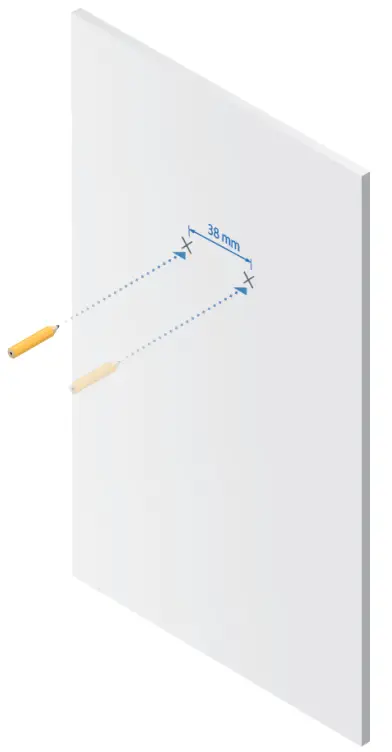
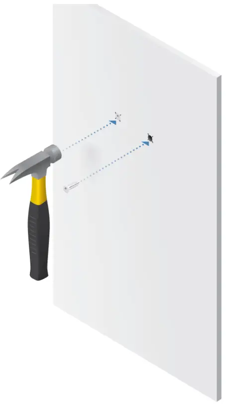
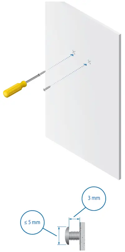
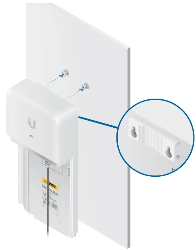
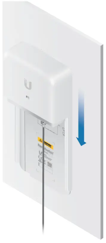
Wall-Mounting
- (2) Screws (≤ 5 mm Screw Head)
- (1) Drain Wire, Optional (≤ 12 AWG, ≤ 1 m)
Cables
- Shielded Category 5 (or above) cabling with drain wire should be used for all wired Ethernet connections and should be grounded through the AC ground of the PoE. We recommend that you protect your networks from harmful outdoor environments and destructive ESD events with industrial-grade, shielded Ethernet cable from Ubiquiti. For more details, visit: ui.com/toughcable
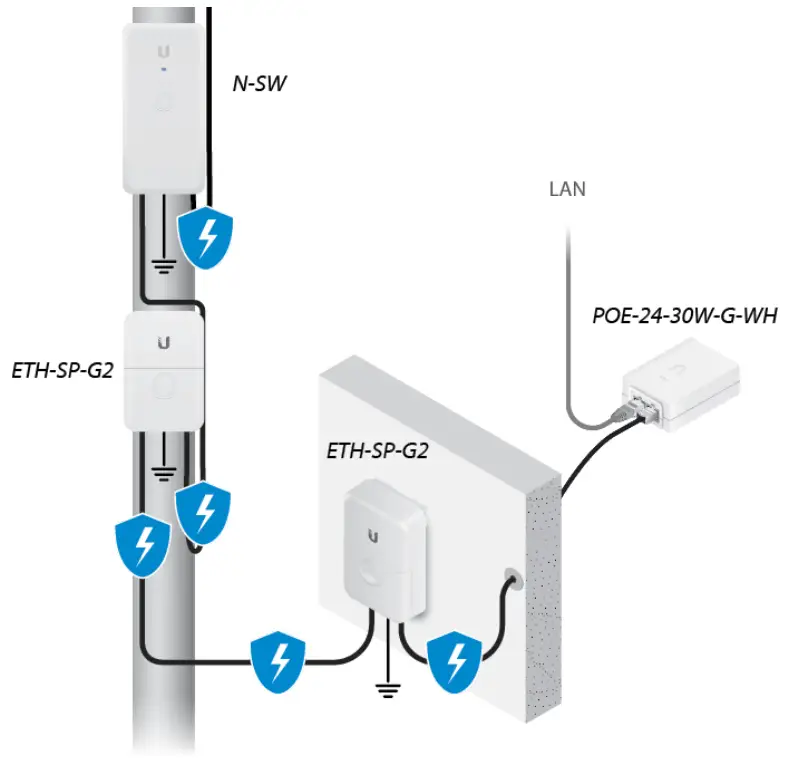
- Surge protection should be used for all outdoor installations. We recommend that you use two Ethernet Surge Protectors, model ETH-SP-G2, one near the N-SW and the other at the entry point to the building. The ETH-SP-G2 will absorb power surges and safely discharge them into the ground.
Hardware Overview
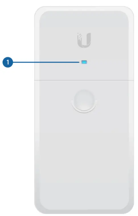
| 1. Power LED | |
| The Power LED will light blue when the device is connected to a power source. | |
| 2. PoE LED | |
| Green | Active 24V PoE |
| 3. Link LED | |
| Green | Link EstablishedFlashing Indicates Activity |
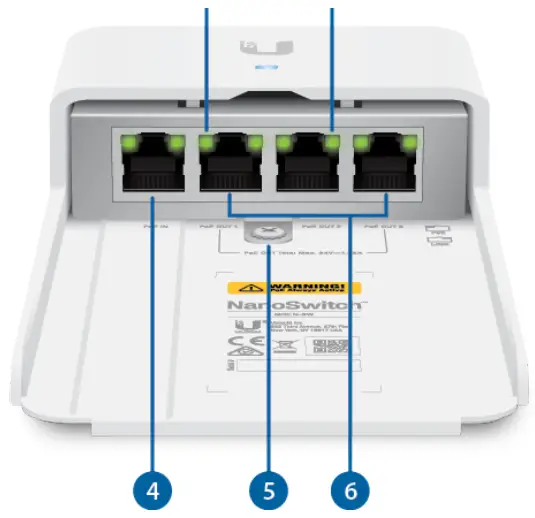
| 4. PoE In Port | |
| RJ45 port supports 10/100/1000 Ethernet connections and supports 24V, 2-pair passive PoE to power the switch. For maximum power consumption of 30W, we recommend supplying power with the POE-24-30W-G-WH PoE adapter (not included). | |
| 5. Ground Bonding Point | |
The NanoSwitch must be grounded in one of the following ways:
|
|
| 6. PoE Out (Ports 1 – 3) | |
| RJ45 ports support 10/100/1000 Ethernet connections and provide passive 24V, 2-pair PoE passthrough for up to 30W PoE output.WARNING: PoE is always active. Before connecting a device to a PoE Out port |
|
| WARNING: Do NOT provide more than a total of 24W PoE output (24V, 1A) per port or 30W total output; otherwise this will damage the NanoSwitch. |
Connect a Drain Wire (Optional)
If a drain wire is used to ground the NanoSwitch, attach it to the Ground Bonding Point with the Self-Tapping Screw and Nut.
At the installation site, secure the other end of the drain wire to a grounded mast, pole, tower, or grounding bar.Hardware InstallationFollow the appropriate steps for your installation:
- “Pole-Mounting”
- “Wall-Mounting”
Pole-Mounting
1. If you are using the Self-Tapping Screw for grounding, remove the Machine Screw and Nut: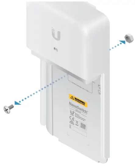
2.
3.
4.
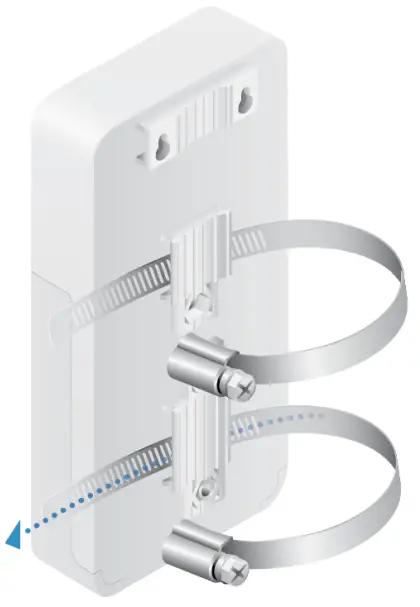
 Note: If you are using a drain wire for grounding, proceed to “Connecting Power”.
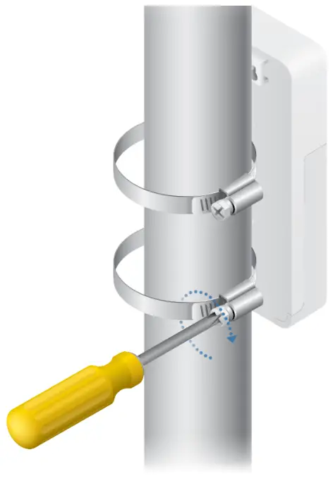
5.
6.
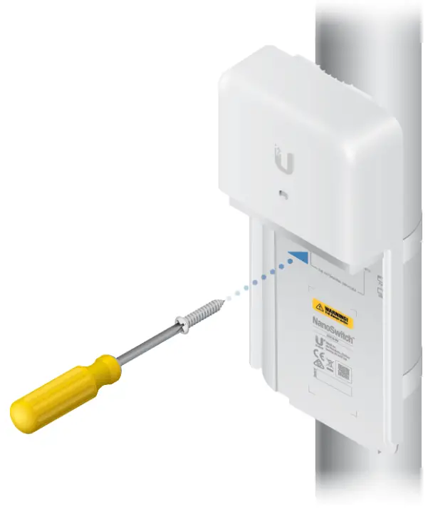
Note: Screws not included.
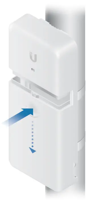
Connecting Power
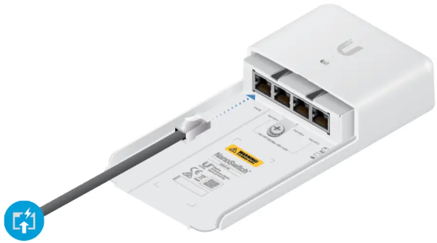
Connecting Ethernet
Specifications
| N-SW | |
| Dimensions (Excluding Mount) | 196A x 93.5 x 314 mm ( 7.73 x 3.68 x 1.28i |
| Weight | 271 g (94 oz) |
| Ensure Characteristics | White Polycarbonate |
| Total Non-Blocking Line Rate | 4 Gbps |
| Typical Power Consumption | 1.5W |
| Max. Power Consumption | 30W |
| Power Method | 24V, 2-Pair Passive PoE |
| Networking Interfaces | (4) 10/100/1000 Mbps Ethernet Ft145 |
| Total Passive PoE Max Wattage | 24V, 2-Pair, lA for 3 Ports (30W) |
| Passive PoE Max Wattage per Port | 24V, 2-Pair, 1 A per Port (24W) |
| Passive PoE Voltage Range | 214 – 30V |
| ESD/EMP Protection | ± 24kV Air, ± 24kV Contact |
| Operating Temperature | -30 to 70°C (-22 to 158° F) |
| Operating Humidity | 5 to 95% Noncondensing |
| Certifications | CE, FCC, IC |
Safety Notices
- Read, follow, and keep these instructions.
 WARNING: Do not use this product in a location that can be submerged in water.WARNING: Avoid using this product during an electrical storm. There may be a remote risk of electric shock from lightning.
Electrical Safety Information
- Compliance is required with respect to voltage, frequency, and current requirements indicated on the manufacturer’s label. Connection to a different power source than those specified may result in improper operation, damage to the equipment, or pose is a hazard if the limitations are not followed.
- There are no operator serviceable parts inside this equipment. Service should be provided only by a qualified service technician.
Limited Warranty
ui.com/support/warrantyThe limited warranty requires the use of arbitration to resolve disputes on an individual basis, and, where applicable, specify arbitration instead of jury trials or class actions.
Compliance
FCC
Changes or modifications not expressly approved by the party responsible for compliance could void the user’s authority to operate the equipment.This device complies with Part 15 of the FCC Rules. Operation is subject to the following two conditions.
- This device may not cause harmful interference, and
- This device must accept any interference received, including interference that may cause undesired operation.
This equipment has been tested and found to comply with the limits for a Class A digital device, pursuant to Part 15 of the FCC Rules. These limits are designed to provide reasonable protection against harmful interference when the equipment is operated in a commercial environment. This equipment generates, uses, and can radiate radio frequency energy and, if not installed and used in accordance with the instruction manual, may cause harmful interference to radio communications. Operations of this equipment in a residential area is likely to cause harmful interference in which case the user will be required to correct the interference at his own expense.
ISED Canada
CAN ICES-3(A)/NMB-3(A)
Australia and New Zealand
 Warning: This equipment is compliant with Class A of CISPR 32. In a residential environment, this equipment may cause radio interference.
CE Marking
![]()
WEEE Compliance StatementDeclaration of Conformity
Online Resources

© 2020 Ubiquiti Inc. All rights reserved.
References
[xyz-ips snippet=”download-snippet”]