US-XG-6POE Quick Start Guide
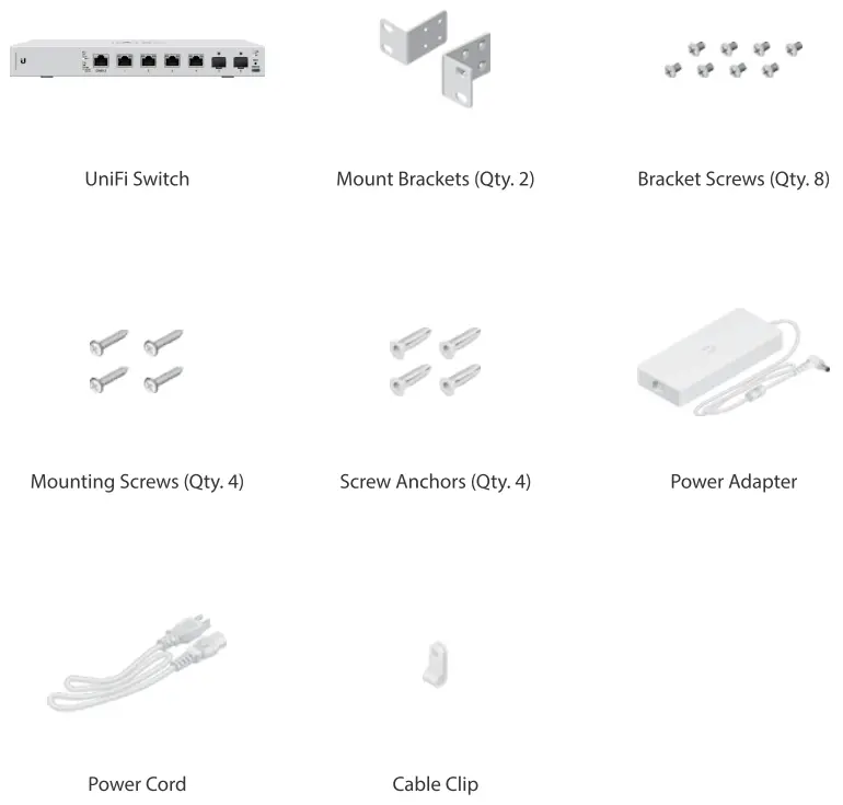
Package Contents
System Requirements
- Linux, Mac OS X, or Microsoft Windows 7/8/10
- Java Runtime Environment 1.8 or above recommended
- Web Browser: Google Chrome (Other browsers may have limited functionality)
- UniFi Controller software v5.8.x (or newer), available at: ui.com/download/unifi
Hardware Overview
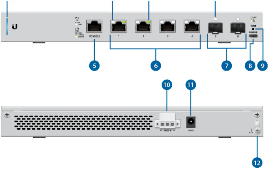
| 1. System LED | |
| Flashing White | Initializing. |
| Steady White | Factory defaults, waiting for adoption. |
| Alternating White/Blue | The device is busy; do not touch or unplug It. This usually indicates that a process such as a firmware upgrade is taking place. |
| Steady Blue | Successfully adopted by a network and working properly. |
| Flashing Blue | This Is used to locate a device.When you click Locate in the UniFi Controller software, the System LED will flash blue. The software will also display the location of the UniFi Switch on the map. |
| 2. RJ45 PoE LED (Ports 1 – 4) | |
| Off | PoE Disabled |
| White | 802.3af/at/bt PoE |
| 3. RJ4S Link/Speed/Activity LED (Ports 1- 4) | |
| Off | No Link |
| Green | Link Established at 1 GbpsFlashing Indicates Activity |
| 4. SFP+ Unk/Speed/Activity LED (Ports 5 – 6) | |
| Off | No Link |
| Green | Link Established at 1 GbpsFlashing Indicates Activity |
| White | Link Established at 10 Gbps Flashing Indicates Activity |
| 5.RJ45 Console Port | |
| RJ45 serial console port for Command Line Interface (CLI) management Use an RA5-toDB9, serial console cable, also known as a rollover cable, to connect the Console port to your computer. Then configure the following settings as needed:•Baud rate 115200•Data bits 8•Parity NONE•Stop bits 1•Flow control NONE | |
| 6. RJ45 (Ports 1 – 4) | |
| RJ45 ports support 100 Mbps or 1/2.5/5/10 Gbps Ethernet connections and 8023af/at/bt PoE output | |
| 7. SFP+ (Ports 5 – 6) | |
| Hot-swappable SFP+ ports support 1/10 Gbps connections.8. USB Console Port | |
| USB Type C console port for Command Une Interface (CLI) management. | |
| 9. Reset Button | |
| This button serves two functions for the UniFi Switch:•Restart Press and release the Reset button quickly.•Restore to Factory Default Settings Press and hold the Reset button for more than five seconds. | |
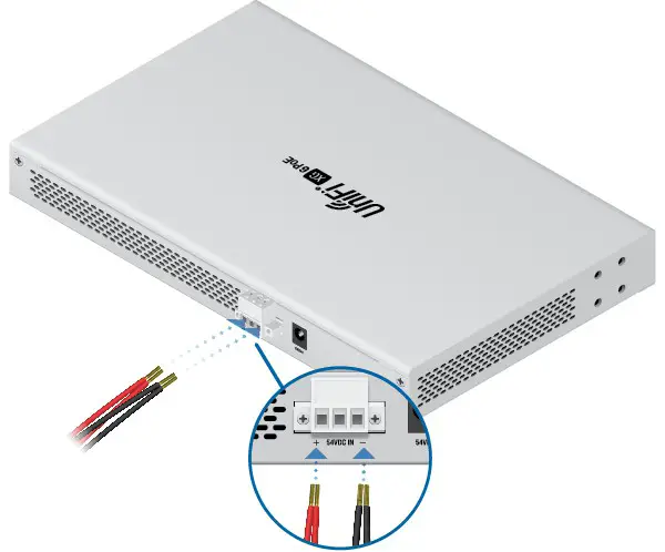
| 10. DC Input | |
| Optional DC Input for connecting a stand-alone or redundant DC power source (not included) with minimum power:40W, 44 to 57VDC.Note: Ensure the polarity Is correct red Is positive (+) and black Is negative (-). You can use the redundant DC power source as a hot spare; if there is no longer power through the Power port, the UniFi Switch will switch to the DC power source without interrupting its operation. |
| 11. Power Port |
| Connect the Included Power Adapter to the Power port. |
| 12. Ground |
| Ancillary grounding point for enhanced ESD protection. |
Hardware Installation
The UniFi Switch can be mounted on a horizontal or vertical surface.![]() WARNING: The US-XG-6POE must not be stacked. Do not place it on top of another switch. Do not place anything on top of the US-XG-6POE.
WARNING: The US-XG-6POE must not be stacked. Do not place it on top of another switch. Do not place anything on top of the US-XG-6POE.
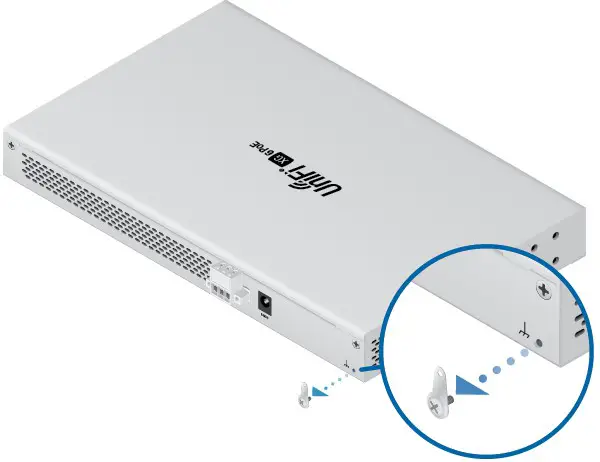
Grounding (Recommended)
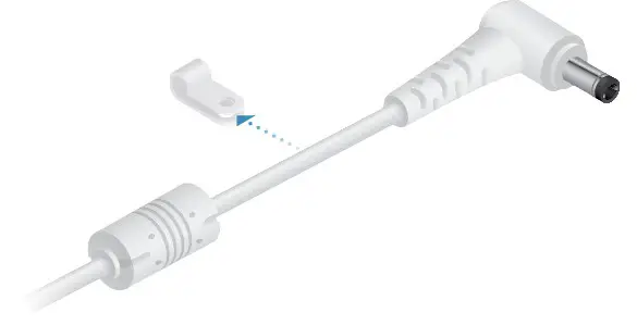
The UniFi Switch is grounded through the Power Adapter; however, you can add optional ESD grounding for enhanced ESD protection.![]() Note: You also have the option to use the Cable Clip to secure the cord of the Power Adapter. For instructions, proceed to “Using the Cable Clip (Optional)”.
Note: You also have the option to use the Cable Clip to secure the cord of the Power Adapter. For instructions, proceed to “Using the Cable Clip (Optional)”.

Using the Cable Clip (Optional)
1.
2.
3.

4.
Connecting Power
You have two options:
- “Using the Power Adapter”
- “Using the DC Input (Optional)”
Using the Power Adapter
1.
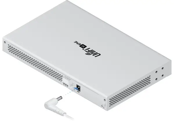
2.

Using the DC Input (Optional)
For stand-alone power or redundant backup, connect a DC power source to the UniFi Switch.Note: Only one power source can be used at any one time. With both power sources connected, the input with the highest voltage will be used; the other power source defaults to backup.Wire a DC/DC cable (not included) to the DC Input. Ensure the polarity is correct: red is positive (+) and black is negative (-).
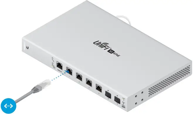
Connecting Ethernet
Connecting SFP+
1.
2.
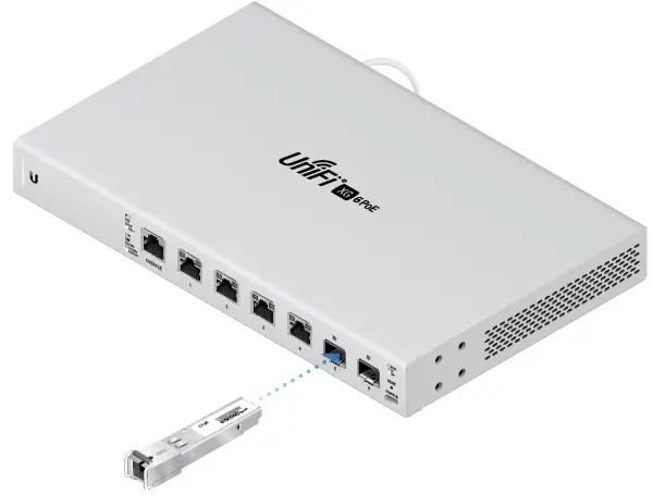
For information about compatible ber SFP modules, visit: community.ubnt.com/uni
Software Installation
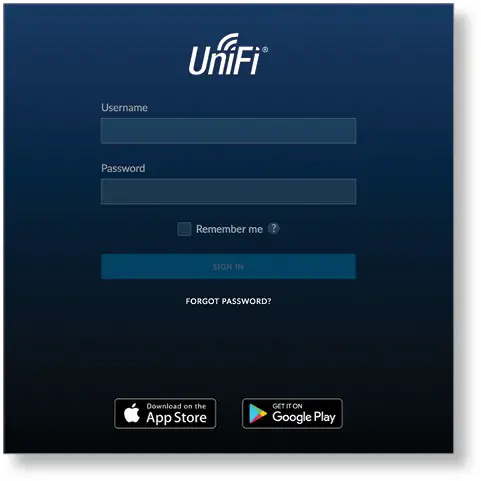
Download and install the latest version of the UniFi Controller software at ui.com/download/uni and follow the on-screen instructions.Note: If you already have UniFi Controller v5.8.x or newer installed, skip to the section, “Adopting the UniFi Switch”.After you have installed the software and run the UniFi Installation Wizard, a login screen will appear for the UniFi Controller management interface. Enter the admin name and password that you created and click Sign In.
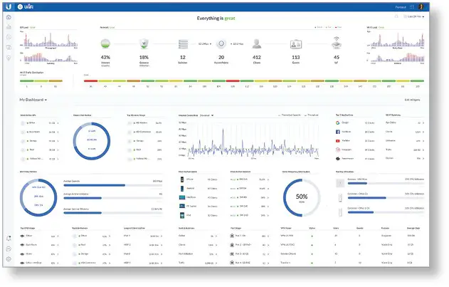
You can manage your network and view network statistics using the UniFi Controller management interface.To adopt the UniFi Switch, proceed to the section, “Adopting the UniFi Switch”.For information on configuring and using the UniFi Controller software, refer to the User Guide on the website: ui.com/download/uni
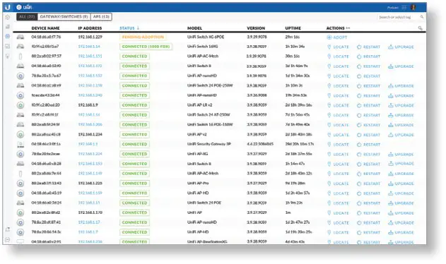
Adopting the UniFi Switch
- From the UniFi Controller dashboard, click Devices in the left menu bar.

- On the Devices screen, locate the UniFi Switch in the list of devices under the Model column. To adopt the UniFi Switch, click Adopt.
- The System LED on the UniFi Switch will turn blue to confirm that it has been successfully adopted.
Specifications
| Dimensions | 165 x 268.1 x 31.8 mm (6.50 x 10.56 x 1.25°) |
| Weight | 1.3 kg (2.87 lb) |
| Interfaces NetworkingManagement | (4) 100 Mbps or 1/2.5/5/1OG 8145 Ports (2) 1/10G SFP+ Ethernet PortsEthernet In-Band (1) R145 Serial Port Out-of-Band (1) US8 Type C Port Out-of-Band |
| Power Method | saw( 3.88A Power Adapter (Included) or 44 to 57VDC, 556A DC Input with Terminal Block |
| Power Supply | External AC/DC Adapter (Included)orDC Power Source |
| Supported Voltage Range | 44 to 57VDC |
| Max. Power Consumption (Exuding PoE Output) | 40W |
| LEDsSystem8145 Data Ports SFP+ Data Ports | StatusPoE; Speed/Link/ActIvItyLink/Activity |
| ESD/EMP Protection | Ain* 18 kV, Contact *12 kV |
| Shock and Vibration | ET5I300-019-1A Standard |
| Operating Temperature | -5 to45°C(23 to 113° F) |
| Operating Humidity | 5 to 95% Noncondensing |
| PoE | |
| PoE Interfaces | PoE++ IEEE 802.3bt(Pair A 1, 2+; 3, 6-) (Pair B 4 , 5+; 7, 😎 |
| Max. 8023bt Wattage per Port by PSE | 60W |
| Voltage Range 8023af Mode | 44-5N |
| Voltage Range 8023at/bt Mode | 50-57V |
Safety Notices
- Read, follow, and keep these instructions.
- Heed all warnings.
- Only use attachments/accessories specified by the manufacturer.WARNING: Failure to provide proper ventilation may cause re hazard. Keep at least 20 mm of clearance next to the ventilation holes for the adequate arrow.WARNING: To reduce the risk of re or electric shock, do not expose this product to rain or moisture.WARNING: Do not use this product in a location that can be submerged in water.WARNING: Avoid using this product during an electrical storm. There may be a remote risk of electric shock from lightning.
Electrical Safety Information
- Compliance is required with respect to voltage, frequency, and current requirements indicated on the manufacturer’s label. Connection to a different power source than those specified may result in improper operation, damage to the equipment, or pose is a hazard if the limitations are not followed.
- There are no operator serviceable parts inside this equipment. Service should be provided only by a qualified service technician.
- This equipment is provided with a detachable power cord which has an integral safety ground wire intended for connection to a grounded safety outlet.a. Do not substitute the power cord with one that is not the provided approved type. Never use an adapter plug to connect to a 2-wire outlet as this will defeat the continuity of the grounding wire.b. The equipment requires the use of the ground wire as a part of the safety certification, medication or misuse can provide a shock hazard that can result in serious injury or death.c. Contact a qualified electrician or the manufacturer if there are questions about the installation prior to connecting the equipment.d. Protective earthing is provided by a Listed AC adapter. Building installation shall provide appropriate short-circuit backup protection.e. Protective bonding must be installed in accordance with local national wiring rules and regulations.
Limited Warranty
ComplianceFCC
Changes or modifications not expressly approved by the party responsible for compliance could void the user’s authority to operate the equipment.This device complies with Part 15 of the FCC Rules. Operation is subject to the following two conditions.
- This device may not cause harmful interference, and
- This device must accept any interference received, including interference that may cause undesired operation.
This equipment has been tested and found to comply with the limits for a Class A digital device, pursuant to Part 15 of the FCC Rules. These limits are designed to provide reasonable protection against harmful interference when the equipment is operated in a commercial environment. This equipment generates, uses, and can radiate radio frequency energy and, if not installed and used in accordance with the instruction manual, may cause harmful interference to radio communications. Operations of this equipment in a residential area is likely to cause harmful interference in which case the user will be required to correct the interference at his own expense.
ISED Canada
CAN ICES-3(A)/NMB-3(A)
Australia and New Zealand
 Warning: This equipment is compliant with Class A of CISPR 32. In a residential environment, this equipment may cause radio interference.
CE Marking
CE marking on this product represents the product is in compliance with all directives that are applicable to it.
WEEE Compliance Statement
Declaration of ConformityOnline Resources
![]()
 report this ad
© 2020 Ubiquiti Inc. All rights reserved.
References
[xyz-ips snippet=”download-snippet”]