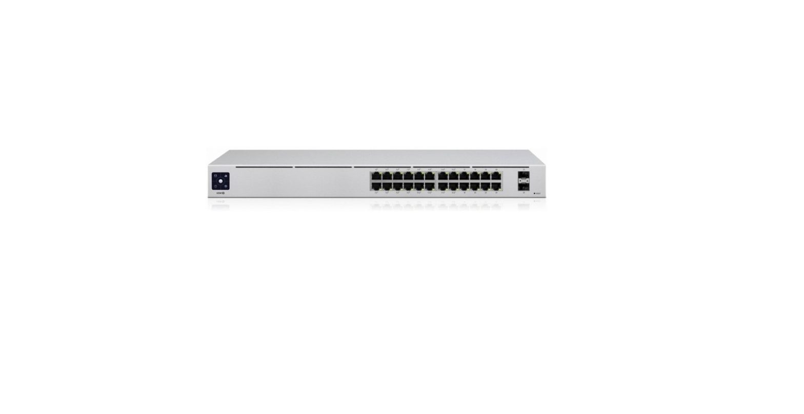
UBIQUITI USW-24 24-Port Managed Gigabit Managed Switch with SFP User Guide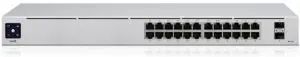
Package Contents
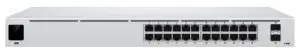
- UniFi Switch

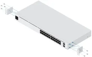
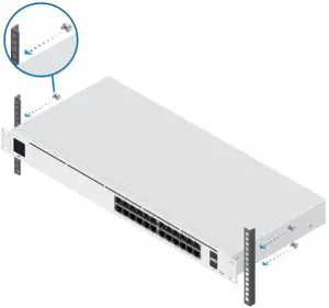
- Rack-Mount Brackets (Qty. 2)
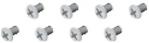
- Bracket Screws (Qty. 8)
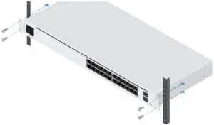
- Mounting Screws (Qty. 4)
- Cage Nuts (Qty. 4)
- Power Cord
System Requirements
Linux, Mac OS X, or Microsoft Windows 7/8/10Java Runtime Environment 1.6 (1.8 or newer recommended)Web Browser: Google Chrome (Other browsers may have limited functionality.)UniFi Controller software v5.12.x (or newer), available at: ui.com/download/uni
IMPORTANT: We strongly recommend using UPS backup and power regulation to prevent equipment damage due to stability issues with local AC power.
Hardware Overview

|
Touchscreen Display |
|
|
Bootup Animation |
Initializing. |
|
Steady White |
Factory defaults, waiting for adoption. |
|
Steady Blue |
Successfully adopted by a network and working properly. |
|
Location Animation |
This indicates that you clicked Locate in the UniFi Controller software. The software will also display the location of the device on the map. |
|
RJ45 Speed/Link/Activity LED (Ports 1 – 24) |
|
|
Off |
No Link |
|
Amber |
Link Established at 10/100 Mbps Flashing Indicates Activity |
|
Green |
Link Established at 1000 Mbps Flashing Indicates Activity |
|
SFP Link/Activity LED (Ports 25 – 26) |
|
|
Off |
No Link |
|
Green |
Link Established at 1 Gbps Flashing Indicates Activity |
|
RJ45 (Ports 1 – 24) |
|
|
RJ45 ports support 10/100/1000 Ethernet connections. |
|
|
SFP (Ports 25 – 26) |
|
|
Hot-swappable SFP ports support 1 Gbps connections. |
|
|
Reset Button |
|
| This button serves two functions for the UniFi Switch: Restart Press and release the Reset button quickly.Restore to Factory Default Settings Press and hold the Reset button for more thanfive seconds.Connect the included Power Cord to the Power port |
Installation Requirements
- Phillips screwdriver
- Standard-sized, 19″ wide rack with a minimum of 1U height available
- For indoor applications, use Category 5 (or above) UTP cabling approved for indoor use.
- For outdoor applications, shielded Category 5 (or above) cabling should be used for all wired Ethernet connections and should be grounded through the AC ground of the power supply.We recommend that you protect your networks from harmful outdoor environments and destructive ESD events with industrial-grade, shielded Ethernet cable from Ubiquiti. For more details, visit: ui.com/toughcableNote: Although the cabling can be located outdoors, the UniFi Switch itself should be housed inside a protective enclosure.
Hardware Installation
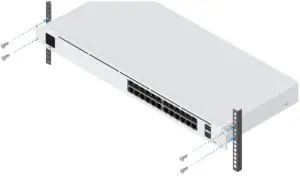
Connecting Power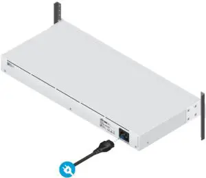 Connecting Ethernet
Connecting SFP
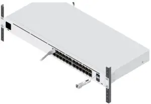

For information about compatible ber SFP modules, visit: ubnt.link/UniFi_SFP_DAC_Compatibility
Software Installation
Download and install the latest version of the UniFi Controller software at ui.com/download/uni and follow the on-screen instructions.![]() Note: If you already have UniFi Controller v5.12.x or newer installed, skip to “Adopting the UniFi Switch”.
Note: If you already have UniFi Controller v5.12.x or newer installed, skip to “Adopting the UniFi Switch”.
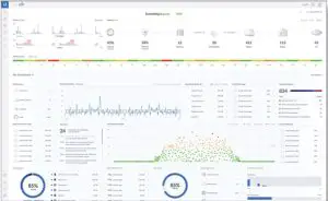
After you have installed the software and run the UniFi Installation Wizard, a login screen will USW-24 appear for the UniFi Controller management interface. Enter the admin name and password that you created and click Sign In. You can manage your network and view network statistics using the UniFi Controller management interface. To adopt the UniFi Switch, proceed to “Adopting the UniFi Switch”. For information on con guring and using the UniFi Controller software, refer to the User Guide on the website: ui.com/download/uni
Adopting the UniFi Switch
- From the UniFi Controller dashboard, click Devices in the left menu bar.
Specifications
| USW-24 | |
| Dimensions | 442.4 x 200 x 43.7 mm (17.42 x 7.87 x 1.72″) |
| WeightWith Rackmount Brackets | 2.70 kg (5.95 Ib)2.79 kg (6.15 Ib) |
| Interfaces NetworkingManagement | (24) 10/100/1000 R145 Ports (2) 1G SFP Ethernet PortsEthernet In-Band |
| Power Method | 100-240VAC, 50/60 Hz, Universal Input |
| Power Supply | AC/DC, Internal, 36W |
| Supported Voltage Range | 100 to 240VAC |
| Max. Power Consumption | 25W |
| LEDs11145 Data Ports SFP Data Ports | Speed/Link/Activity Link/Activity |
| ESD/EMP Protection | Air: ± 16 kV, Contact: ± 12 kV |
| Shock and Vibration | ETSI300-019-1.4 Standard |
| Operating Temperature | -5 to 45° C (23 to 113°F) |
| Operating Humidity | 10 to 90% Noncondensing |
| Certifications | CE, FCC, IC |
Safety Notices
- Read, follow, and keep these instructions.
- Heed all warnings.
- Only use attachments/accessories specified by the manufacturer.
![]() WARNING: Failure to provide proper ventilation may cause re hazard. Keep at least 20 mm of clearance next to the ventilation holes for adequate air ow.
WARNING: Failure to provide proper ventilation may cause re hazard. Keep at least 20 mm of clearance next to the ventilation holes for adequate air ow.
![]() WARNING: To reduce the risk of re or electric shock, do not expose this product to rain or moisture.
WARNING: To reduce the risk of re or electric shock, do not expose this product to rain or moisture.
![]() WARNING: Do not use this product in location that can be submerged by water.
WARNING: Do not use this product in location that can be submerged by water.
![]() WARNING: Avoid using this product during an electrical storm. There may be a remote risk of electric shock from lightning.
WARNING: Avoid using this product during an electrical storm. There may be a remote risk of electric shock from lightning.
Electrical Safety Information
- Compliance is required with respect to voltage, frequency, and current requirements indicated on the manufacturer’s label. Connection to a different power source than those speci ed may result in improper operation, damage to the equipment or pose a re hazard if the limitations are not followed.
- There are no operator serviceable parts inside this equipment. Service should be provided only by a quali ed service technician.
- This equipment is provided with a detachable power cord which has an integral safety ground wire intended for connection to a grounded safety outlet. a. Do not substitute the power cord with one that is not the provided approved type. Never use an adapter plug to connect to a 2-wire outlet as this will defeat the continuity of the grounding wire. b. The equipment requires the use of the ground wire as a part of the safety certi cation, modi cation or misuse can provide a shock hazard that can result in serious injury or death. c. Contact a quali ed electrician or the manufacturer if there are questions about the installation prior to connecting the equipment. d. Protective earthing is provided by Listed AC adapter. Building installation shall provide appropriate short-circuit backup protection. e. Protective bonding must be installed in accordance with local national wiring rules and regulations.
Limited Warranty
ui.com/support/warranty The limited warranty requires the use of arbitration to resolve disputes on an individual basis, and, where applicable, specify arbitration instead of jury trials or class actions.Compliance
FCCChanges or modi cations not expressly approved by the party responsible for compliance could void the user’s authority to operate the equipment. This device complies with Part 15 of the FCC Rules. Operation is subject to the following two conditions.
1. This device may not cause harmful interference, and
2. This device must accept any interference received, including interference that may cause undesired operation.
USW-24 Quick Start Guide
This equipment has been tested and found to comply with the limits for a Class A digital device, pursuant to Part 15 of the FCC Rules. These limits are designed to provide reasonable protection against harmful interference when the equipment is operated in a commercial environment. This equipment generates, uses, and can radiate radio frequency energy and, if not installed and used in accordance with the instruction manual, may cause harmful interference to radio communications. Operations of this equipment in a residential area is likely to cause harmful interference in which case the user will be required to correct the interference at his own expense.
ISED CanadaCAN ICES-3(A)/NMB-3(A)
Australia and New Zealand![]() Warning: This equipment is compliant with Class A of CISPR 32. In a residential environment this equipment may cause radio interference.
Warning: This equipment is compliant with Class A of CISPR 32. In a residential environment this equipment may cause radio interference.
CE MarkingCE marking on this product represents the product is in compliance with all directives that are applicable to it.
WEEE Compliance Statement
 report this ad
Declaration of Conformity
Online Resources


 © 2020 Ubiquiti Inc. All rights reserved.
References
[xyz-ips snippet=”download-snippet”]