Instruction Manual


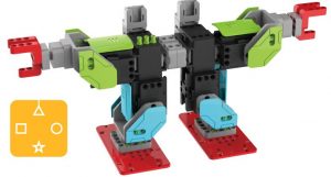
UBTECH Jimu Robot MeeBot 2.0
Components Introduction
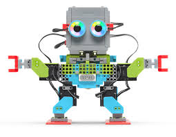
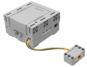
Main Control Box
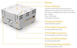
The brain of a Jimu robot is a Main control box. Once the mobile phone has connected over wireless to the main control box, it can be used to control the Jimu robot. There is an exclusiveMAC address for the controller on its back. The Main control box has slots, plugs and ports,which allows the robot be assembled by splicing, integrating, and connecting.
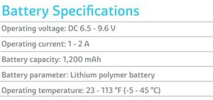
Battery
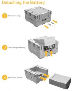
The battery comes factory-installed on the main control box. You can also replace the battery. Remove the plugs on the downside before disassembling the battery from the main control box. Install the replacement battery into the controller and then secure the plugs.
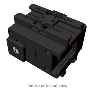
Servos
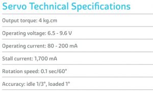
Servos are like human joints. They are the keys for the Jimu robot to perform movements.
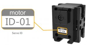
Servo IDEach servo has an ID number to distinguish it from the other servos. Please see “Connecting Model – Changing Servo ID” for more details.
SlotsThere are 5 slots on the servo with which the rudder can be spliced, namely “ABCDE”. For more details, please see: “Assembly Introduction – Splicing”.
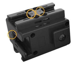
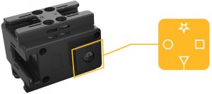
Rotatable RuddersThe rudders of the servo can rotate, and it can also be spliced with slots. “△□☆○” indicates different splicing directions. When “△” is aligned with the scale, the angle of the rotatable rudder is 0°. For more information regarding the use of servo rudders and other components assembly, please see: “Assembly Introduction: Splicing”.
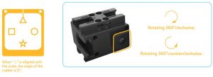
Servo Rotation ModesThere are two different rudder rotation modes.In the normal mode, the rotation range of the rudder is between -120° to 120°. And the time range for it to rotate from one angle to another is 80ms – 5,000 ms. In the wheel mode, the rudder can rotate 360° clockwise or counterclockwise. The rotation speed can be set to “Very slow”, “Slow”, “Normal”, “Fast”, and “Very fast”.
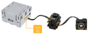
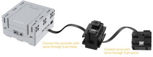
3-Pin PortsEnergy and information can be transmitted between the Main control box and servos. The 3-pin cable can be used to connect controller and servo, or servo and servo 3-pin ports.
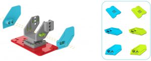
Connectors
Connectors are the skeleton of the robot. Slots or rudders of connectors can be spliced togetherwith other components’ rudders or slots.
Decorating Pieces
The decor Decorating Pieces are the cover of the model and give it a more attractive appearance. Decorating pieces can also be integrated with other components through plugs and attachments.
Power Switch
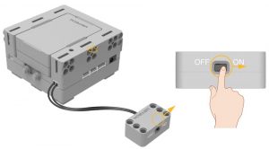
Power allows the Jimu robot to operate. Use the connecting cable to connect the power switch to the Main control box. Turn on/off the power using the power switch.
Decorating Piece – Fasteners
Fasteners can integrate decorating pieces, connectors, the controller, and servos together through holes.
Note: Fasteners come in different shapes, lengths and sizes.
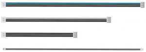
Connecting Cables
Connecting cables are like blood vessels of the Jimu robot. It can connect the controller with servos, and a servo with another servo. It can also transmit energy and commands between the controller and servos.
Assembly Tool
The assembly tool can help you install and remove components, making the building process of your model simpler and easier.
The end of the assembly tool is a clip. It can clip onto connectors to remove them from the components, or install them into the components.
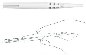
Use method
Assembly Introduction
Key Parts
- Slots: The slot is a groove in components, which usually appears on connectors and servos. When a component has multiple slots, the “ABCDE” naming method will be used to distinguish them.
- Rudders: Rudders are rectangular structures projecting from components. The symbols “△□☆○” are used to indicate the different directions.
- Plugs: Plugs on components come in different shapes and sizes, and are compatible with different fasteners.
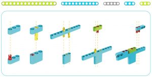
Assembly Methods
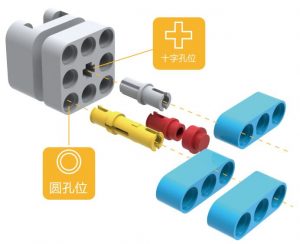
a. Splicing: Splicing refers to connecting rudders with slots.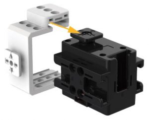 1. “△□☆○” on the surface of the rudder correspond with different splicing directions of slots. Different splicing directions can yield different structures.
Example of connecting other components with rudders
2. If a component has multiple slots, it can be assembled into different structures.
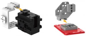
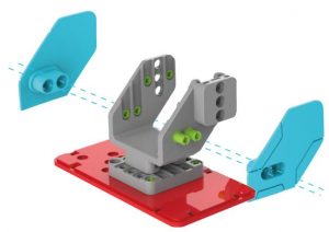
b. Integration:
Integration refers to the method of assembling different components through fasterners.
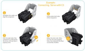
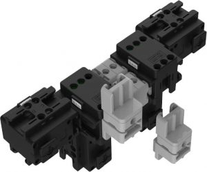
c. Connection: Connection refers to the assembly method of connecting the Main control box with servos, servos with servos, the Main control box with sensors, or the Main control box with power switch using connecting cables.
- Connection between the Main control box and servos, or servos and servos. The Main control box can be connected to up to 7 servos through 3-pin ports. A servo can be connected to 32 servos at most.
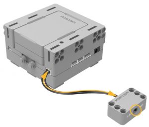
2. Connection between the Main control box and power switch.The power switch can be connected to the Main control box through 2-pin ports to turn on/off the Main control box.
Jimu APP
Even though it is a lot of fun to assemble the robot, it is even more fun to give life to the robot, allowing it to move and complete tasks. You can use the Jimu app to achieve this.
Getting the Jimu App
Jimu Robot must be used in conjunction with the Jimu app. First, you need to download the Jimu app:
- iOS: Search and download Jimu in the App Store;
- Android: On an Android device, search for “Jimu” in Android Play, Android App Store, or other App stores. Download, and install Jimu app;
- Go to http://www.ubtrobot.com/app.asp in the browser, download the software and install it.
Using Ubtech Account to Log in
Users can use the Ubtech account to log in and use our products, including the “Alpha1s App”, “Alpha 2 App”, and “Jimu” app. Within the Jimu app, you can select “Email”, “Mobile phone”, or “Third party account login” to register a Ubtech account.
After successfully registering, you can log in and use our corresponding products. Users under the age of 13 must register an account under the guidance of their parents. You do not need to log in to use the app.

Learn to Build
Jimu is a unique product, and having the necessary basic knowledge will better enable you to let your imagination fly.
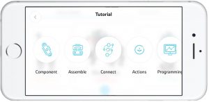
Tutorial:
The app includes images, texts, and videos to support you more. The tutorial provides an introduction to the basic rules of building. It is designed to help users get familiar with our products faster. It includes 5 basic sections, namely Components, Assembly, Connection, Movement, and Programming.
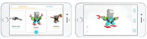
Official Models
In addition, a series of carefully designed official models have been also provided, allowing the users to apply the building knowledge they have learned and get familiarized with the main functions.
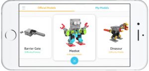
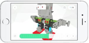
a: Select a specific model, and enter the Model Details page. Using the official 3D models provided, you can view the details of the model in 360° on your mobile phone. You can also use the Dynamic Drawings function, and follow the 3D interactive animation step-by-step to build the model.
b: After building the actual model, you can connect your actual model by pressing the Connect button on the Model Details page; see “Wireless Connection” for details.

Wireless Connection
Wireless connection refers to connecting the app on your mobile phone to the main control box via bluetooth. Both the official models and those designed by you require connection to the Jimu app to allow control on the robot.
Wireless Connection Process and Connection Requirements
a. Switching on the Main control box Power: Switch the power button from the off position to the on position; when the Main control box’s power indicator is flashing green, it means that it has been successfully turned on.
b. Turning on the Bluetooth;c. Selecting the Model You Want to Connect in the App;
d. Finding the Controller
When connecting for the first time, find the Bluetooth device called “Jimu”. If you have renamed the Bluetooth device, then find the renamed Bluetooth device.
For Android devices, please find the device’s MAC address.
e. Connecting the Controller
Select the Bluetooth device you want to connect, and establish a connection with the controller. If you are using an Android device, please select and connect the model that has the same MAC address as your controller. Once the connection has been established, the controller will detect whether the hardware matches the model data in the app. The following requirements must be satisfied for a successful connection:
- The number of servos should be consistent
Once the connection has been established, the app will use the servos number of the model in the software as a reference, and compare it with the servos number of the actual model to check if the numbers match. If the numbers do not match, the user can check the number of the actual model servos according to the prompt error messages. Then reconnect.
Troubleshooting:
- Check whether the model has been completed according to the steps in “Build”.
- Check whether changes has been made to the model.
- Check whether the app has been connected to the wrong model or controller.

2. The servo IDs should be consistent
In addition to comparing the number of servos, the app will also compare to see if the servo ID of the actual model matches the model in the software. When the servo ID of the actual model does not match the servo ID of the model in the software, the user can check the servo ID in the models that does not match according to the prompt error message. Then enter the Edit Servo ID page and change the ID.
Troubleshooting:
- When the servo IDs are different: Change the servo with the different ID to the servo with the same ID;
- When the servo IDs are repeated: Edit the repeated servo ID.

3. The servo firmware versions should be consistent
If the servo firmware versions do not match, the app will perform a mandatory upgrade to the servo. During upgrading, battery power level has to be maintained at over 50%. If battery power is lower than 50%, upgrading cannot be completed, and the wireless connection will be disconnected.
After your mobile device is successfully connected to the controller, you can view the battery power level of the model and the connection status on the connected Model Details page.
Controller
You can add movements to the controller. This way, you can control your robot as if you are playing a video game.
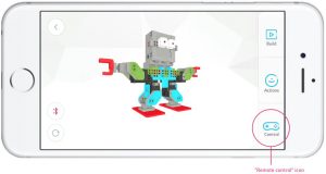
a.Using the Controller
Enter the remote control page. With the configured remote control, you can directly press the corresponding buttons to have the robot perform the corresponding movements.
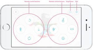
b. Editing the Controller
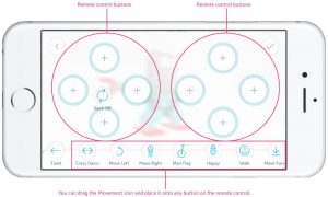
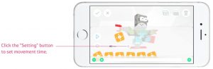
If you have not configured the remote control, you can press the Settings button on the top right corner to enter the Remote Control Configuration page. In this page, all of the movements that you have added to the model will show up on the Movement bar at the bottom of the page.
Drag the Movement icon and place it onto a certain button on the remote control. If a movement has already been added to that button, the new movement you dragged will replace the existing one.
Movement Introduction
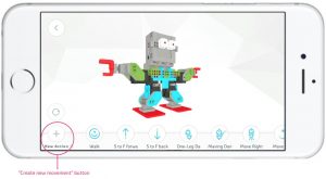
1. Creating Movements
2. Movement Principle
Before building a new movement, you might need to know the movement principle of Jimu.
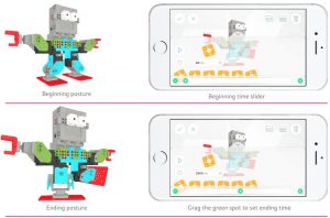
Movement refers to the process by which the model changes from one posture to another one within a period of time. The movement can be defined through time setting and posture adjustment.
3. Creating Movements
a. Setting Up a Model Posture: There are two ways to set up a posture: Dragging servos and recording a posture.
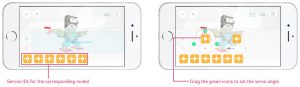
Dragging Servos Open the Movement Programming interface, and all servos of the current model are displayed at the bottom. Each servo corresponds with different joints of the model. You can drag the specific servo of a joint that needs to be moved to the movemen taxis, or you can combine themovements of dragging the servos repeatedly. One servo in the movement axis represents only one robot posture change. The combination of servos represents multiple posture changes at the same time. Select the servo you want to move and enter Servo Editing. You can now configure the servo angle by rotating the control components.
Recording the Posture: Loosen up the robot joints. Adjust the robot posture. Then press the key to record the posture
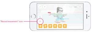
A Record Movement icon will appear on the movement axis after the Jimu robot is connected. Click the icon and the Jimu robot will automatically loosen the joint. You can now adjust the robot into the posture you want. Click the icon again and the posture will be added to the movement axis.
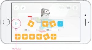
b. Setting Movement TimeThe movement time range is 80 ms – 5,000 ms.Click the corresponding time button for the movement, and the time slider will appear at the bottom of the screen. Slide left or right to quickly configure the movement interval, or click the “Add” and “Subtract” button for micro-adjustment.
c. Previewing a Movement Select the “Play” button in front of the movement axis to preview the movement. If you select a servo, the preview begins with the selected servo posture; if not, you can preview the entire movement.
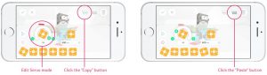
d. Copying and Inserting a Posture In Edit Servo mode, you can copy the current movement. And the insert button at the top-right corner in movement programming page will be activated. You can select another posture and insert the posture copied earlier behind this.
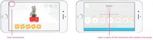
e. Saving a Movement
After completing the design of the movement, choose a name and select an icon for your movement to save the movement. You can view your saved movements in the Movement Bar by their icons and the name of the movements.
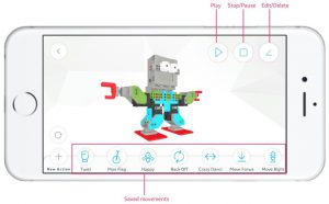
f. Controling a Movement After selecting a specific movement, the control button will appear. You can play/ pause/ stop the movement, or edit and delete the movement.
Creating
The official model is only for you to familiarize yourself with building and using Jimu. The most important recommendation is to apply what you learnt to your own design. You can add items in the Personal Model page to save the progress or result of the Jimu robots that you have built.
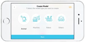
1. Selecting Category
You need to select a category for your model: “Animal”, “Machine”, “Robot”, “Others”. When you share your models with the community, model categories help other users to find your models.
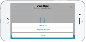
2. Adding Photos
The Jimu app does not support creating 3D models within the app. Because it is different fromthe official models, you will need to add a photo for your model.You can select one from the photo album or directly take a picture of the model.
3. Naming
Assigning the model a memorable name helps your model attract more attention. After successfully naming your robot, you have finished creating your Jimu robot.
You can share the robot you built with the community or on other social platforms. At the same time, you can also discover more models designed by other enthusiasts in our community.
a. Sharing Models Enter the Personal Model page, click the share button at the bottom-right corner to enter the Model Sharing process. In this page, you can add four photos and a video, as well as a description for your model. After adding the necessary information, click the upload button at the top-right corner to upload the model to the community. After successfully uploading, you can also share this model to other social platforms.

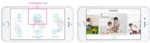
b. Discovering Models Enter the community page from the menu.The models in the community are categorized based on different categories of models uploaded by users. You can see the models’ details, view their photos or videos, like them, view comments posted on them, and even write a comment yourself.
FAQ
1. Hardware
Q: After the robot is turned on, it has no response and the LED light on the Main control box is still off.
A:
- Please ensure the cable connecting the Main control box and the external switch box is properly installed and not damaged.
- Please ensure the battery on the Main control box has been properly installed and that the battery has a good connection with the Main control box’s battery holder.
- Please ensure the battery is not too low. If it is, please recharge the battery.
Q: During the programming process, the robot made a strange “Click Click” sound.A:
- When you are performing angle programming for a single servo motor, if the drag angle is too large, it could cause the joints to rub against each other. When you hear that strange sound, please drag the dot to the opposite direction, and the problem should be solved.
- You can immediately press the action record button, which will power off the servo motor.
- If the battery is too low, please recharge it.
Q: When being remotely controlled, the robot makes a strange “Click Click” sound.A:
- The product is incorrectly assembled. Please check the assembly drawing and see if the servo motor making the strange sound has been installed incorrectly.
- Please check and see if there is an incorrect cable being used on the servo motor which could be making the strange sound, and also check if there is any type of interference or pulling of the cables.
- Check whether the battery is too low.
Q: After the robot is assembled, the entire robot becomes loose or some parts fall off when it performs actions.A:
- Check whether the loose parts are correctly assembled. Once the parts are assembled in place, you should hear a “click” sound.
Q: The robot can’t complete an action.A:
- Please use the robot on a smooth surface.
- The robot’s action poses and the simulated poses on the app must match. If they do not match, it will affect the robot’s action.
- Ensure that the battery is not getting too low.
- Check if all the connecting parts are properly assembled. Once they are assembled in place, you should hear a clap sound.
2. APP
Q: The official model cannot be downloaded.A:
- Check if there are any Internet connection issues.
- Ensure your cell phone has enough storage space.
- The official server may have malfunctioned, we suggest trying it again at a later time.
Q: The robot’s Bluetooth cannot be found.
A:
- Please ensure the robot is on, and try to search for it again after restarting the app.
- Please ensure your cell phone’s Bluetooth is turned on, and the app has obtained permission to use Bluetooth.
- Restart the robot and have the app try to search it again.
- Please check if the distance between your cell phone and the robot has exceeded the effective range.
- Check if you have used an unofficial software to modify the Bluetooth name.
Q: The mobile device and the robot cannot be connected.A:
- Ensure the app is connected with the correct Bluetooth device.
- Try to connect again after restarting the robot and the app.
Q: The app displays abnormal rotations.A:
- If the servo motor encounters interference during the rotation process, it will activate the locked rotor protection and the abnormal servo motor will then be unlocked. It will recover once the robot has been restarted.
- Please investigate the reasons behind the locked rotor:① If the servo motor has been installed in an incorrect direction, it can cause interference and it needs to be corrected promptly. Otherwise, it will keep reporting an error and it could even burn the servo motor.② Check if the wiring is incorrect or if it is the wrong cable length that is causing the pulling. Use the right cables and rewire immediately.③ If an unofficial model is used, please ensure the design is compatible, including whether or not it surpasses the servo motor’s maximum load.If so, you may consider replacing it with a servo motor with a larger torque.
Q: The app displays abnormal temperatures.A:
- Please allow the robot to rest for half an hour, then you may continue to use it.
Q: The app displays low voltage.A:
- Please recharge the robot, and do not use the robot while it is recharging.
Q: The app displays no connection.A:
- If it still reports an error after re-assembly and/or changing the cables, then the servo motor communication may have malfunctioned. Please replace the servo motor.
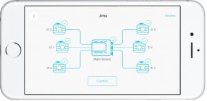
Q: The app displays the quantity of the servo motors do not match when connecting via Bluetooth.A:
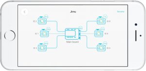
- When the app is connecting via Bluetooth, a network topological graph will be displayed. Please check if there are any errors prompted on this graph.
- Check whether the built robot matches the connected official model.
- Check if there are any connection errors according to the reported errors on the topological graph. If there are errors reported about several servo motors, please check if the cables are properly connected to the ports on the main control box.
Q: The app displays duplicate Servo IDs.A:
- Check if you have bought multiple hardware products and the same ID has been used more than once. You can just find the ID and replace it.
- Check if you have used software to change the ID. We do not recommend changing it carelessly. Please make sure to change the ID sticker after you have modified the ID in order to avoid confusion.
Q: The app displays that the servo motor version or the motherboard version is inconsistent.
A:
- The app has an automatic update feature. If the information is prompted, please ensure the device is connected to the Internet.
Q: The app failed to load the model.A:
- Try switching the type of Internet connection, for example switching to 4G or Wi-Fi.
- It could be a server error. We suggest trying it again at a later time.
UBTECH Jimu Robot MeeBot 2.0 Instruction Manual – UBTECH Jimu Robot MeeBot 2.0 Instruction Manual –
Questions about your Manual? Post in the comments!
[xyz-ips snippet=”download-snippet”]