
![]() User Manual – CX6936/CX8936 FUMBLE
User Manual – CX6936/CX8936 FUMBLE
Technical Data
Radio frequency: 2402 to 2480 MHzTransmission power: 4mWPower supply: 5-24V DCTemperature range: 50° – 131° F operating temperatureRelay connections: DC: max. 48V/0.7A – AC: max. 32V/0.5A
Intended Use
The radio switching module is designed for installation on indoor walls. It is an extension of the locking system with a radio switching unit and establishes a connection to the locking units via radio.
Safety Instructions
- Modifications of any kind whatsoever, except those described in the corresponding manual, are not permitted on the products of Uhlmann & Zacher GmbH.
- Use only original parts and accessories of Uhlmann & Zacher GmbH to prevent malfunctions and damages.
- The products of Uhlmann & Zacher GmbH should not be used for locking emergency life-saving aids (e.g. defibrillator, emergency medication, fire extinguishers, etc).
- The products should not come into contact with paint or acids.
- Do not use the products in potentially explosive areas. The products should only be used within the defined temperature range.
- Electrical equipment should only be installed and assembled by qualified electricians.
- High risk of injury (electrical shock!) if the connecting cables are touched with the power supply switched on.
- Carry out installation and maintenance work only with the power supply switched off. Comply with all applicable national safety codes and standards.
- The manual should be handed over to the user by the person doing the installation.
- Uhlmann & Zacher shall not be liable for any damage to the door or the components in case of improper installation.
- Liability cannot be accepted for units that are wrongly programmed. If there are disruptions, such as access not possible to injured persons, property damage, or other damages, then Uhlmann & Zacher shall not be responsible.
Overview / Included in delivery
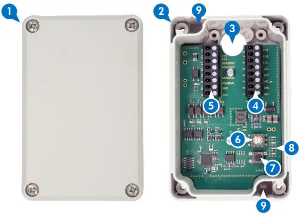
| 1. Lid including srews x42. Base plate with electronics3. Cable inlet4. Removable connector for pin 1-85. Removable connector for pins 9-16 | 6. Rotary switch7. Button8. LEDs9. Mounting hole x2screws are not included |
Installation

- Find a suitable position in the range of the locking unit. Make sure that the surface is smooth, dry, and robust. Do not position several units very closely to make sure their radio does not interfere.
- Mark drilling positions through mounting holes9and drill holes if necessary.Use suitable flat-headed screws and screw anchors if necessary (both not included).If you want to attach the cable from aside, use large enough rubber or plastic spacers to make sure the cable is not squeezed.
- Attach the device to a surface.
Attach the cable to pins as required in your specific project. The two connectors 4and5 for pins 1-8 and 9-16 are both removable. See the table below for the correct pin assignment.Power supply: 5-24 V DC | Relay connections: DC: max. 48V/0.7A – AC: max. 32V/0.5A
| Contact No. | Pin assignment |
| 1 | Positive voltage supply (5 – 24V) |
| 2 | Negative voltage supply (GND) |
| 3 | Input ground |
| 4 | Wiegand 0 |
| 5 | Wiegand 1 |
| 6 + 7 + 8 | Input |
| 9 | Positive voltage supply (5 – 24V) |
| 10 | Negative voltage supply (GND) |
| 11 | RS485A |
| 12 | RS485B |
| 13 | RS485A |
| 14 | RS485B |
| 15 + 16 | Relais |
- To pair the device with a locking unit, the assigned locking unit needs to be in service mode. Usually, the locking unit enters service mode if an authorized service key is presented to the unit.
- Use a screwdriver or a similar tool to set the rotary switch 6 to position 8 then shortly press the button7to change to pairing mode.
- Press the button again to pair the device with a locking unit.
- Close the device with the lid 1by attaching the 4 included screws.
Position: Function: 0 Default position. Press button short to a couple in paired locking unit. 4 Press the button short to enter service-mode 8 Press button short pairing for pairing mode. Press again for pairing unpairing with a locking unit.
FCC Compliance Statement
This device complies with Part 15 of the FCC Rules. Operation is subject to the following two conditions:
- this device may not cause harmful interference, and
- this device must accept any interference received, including interference that may cause undesired operation.Changes or modifications not expressly approved by Uhlmann & Zacher GmbH could void the user‘s authority to operate the equipment.This equipment has been tested and found to comply with the limits for a Class B digital device, pursuant to part 15 of the FCC Rules. These limits are designed to provide reasonable protection against harmful interference in a residential installation. This equipment generates, uses and can radiate radio frequency energy and, if not installed and used in accordance with the instructions, may cause harmful interference to radio communications. However, there is no guarantee that interference will not occur in a particular installation. If this equipment does cause harmful interference to radio or television reception, which can be determined by turning the equipment off and on, the user is encouraged to try to correct the interference by one or more of the following measures:– Reorient or relocate the receiving antenna.– Increase the separation between the equipment and receiver.– Connect the equipment into an outlet on a circuit different from that to which the receiver is connected.– Consult the dealer or an experienced radio/TV technician for help.
Canadian Compliance Statement
This device contains license-exempt transmitter(s)/receiver(s) that comply with Innovation, Science and Economic Development Canada’s license-exempt RSS(s). Operation is subject to the following two conditions:
- This device may not cause interference.
- This device must accept any interference, including interference that may cause undesired operation of the device.
[xyz-ips snippet=”download-snippet”]