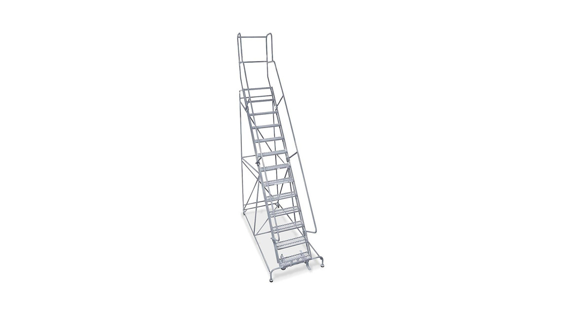
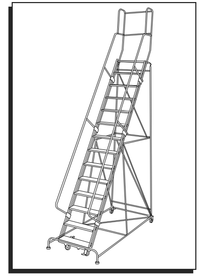
![]() 13-16 STEP ROLLING SAFETY LADDERS10″ DEEP TOP STEP
13-16 STEP ROLLING SAFETY LADDERS10″ DEEP TOP STEP
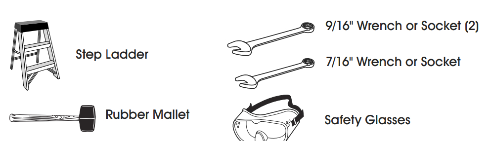
TOOLS NEEDED
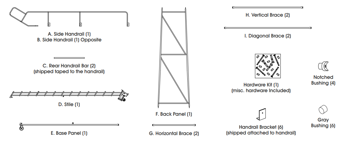
PARTS
ASSEMBLY
![]() WARNING! Assembly of these types of ladders can be inherently dangerous. Please take all necessary precautions during the assembly process. Always use a separate ladder to finish assembly in high places. Never climb a ladder that is not completely assembled. Do not assemble or use a ladder with missing or damaged parts. Use proper lifting mechanics when assembling a ladder. Watch for overhead electrical hazards and obstructions.
WARNING! Assembly of these types of ladders can be inherently dangerous. Please take all necessary precautions during the assembly process. Always use a separate ladder to finish assembly in high places. Never climb a ladder that is not completely assembled. Do not assemble or use a ladder with missing or damaged parts. Use proper lifting mechanics when assembling a ladder. Watch for overhead electrical hazards and obstructions.
STEP 1: FRAME ASSEMBLY![]() NOTE: DO NOT tighten bolts until instructed to.
NOTE: DO NOT tighten bolts until instructed to.![]() NOTE: Back panel (F) has both round and slotted holes. The round holes are at the bottom, and the slotted holes are at the top (L1).
NOTE: Back panel (F) has both round and slotted holes. The round holes are at the bottom, and the slotted holes are at the top (L1).
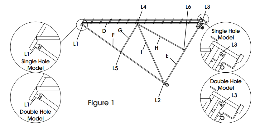
- 1. Place the ladder stile (D) on the floor. Be sure to assemble on a protective surface so the finish does not get damaged. (See Figure 1)
- Using 3/8-16 x 1¼” hex head cap screws and self-locking nuts, bolt the top (slotted hole) of the back panel (F) to the insides of L1. (See Figure 1)
- Bolt the bottom (round hole) of the back panel (F) and back of the base panel (E) to the insides of L2.
- Bolt the front of the base panel (E) to the insides of L3. (See Figure 1)

STEP 2: HORIZONTAL AND VERTICAL BRACE ASSEMBLYNOTE: DO NOT tighten bolts until instructed to.
- Using (3) 3/8-16 x 1¼” hex head cap screws, locate horizontal brace (G) on the outside of L4 and L5.
- Locate the vertical brace (H) on the outside of L4 and L6.
- Start (2) self-locking nuts onto screws at L5 and L6.
![]() WARNING! Never climb a ladder that is not completely assembled.
WARNING! Never climb a ladder that is not completely assembled.

STEP 3: DIAGONAL BRACE ASSEMBLY
![]() NOTE: DO NOT tighten bolts until instructed to.
NOTE: DO NOT tighten bolts until instructed to.
- Locate diagonal brace (I) on the inside of L4 using the existing screws from Step 2, #1, and #2. Start locknut. (See Figure 1)
- Using the screw installed at Step 1, #2, locate another end of the diagonal brace (I) on the inside of L2 and start locknut.
- Repeat steps 2 and 3 to another side.
STEP 4: INSTALL HANDRAILS![]() NOTE: DO NOT tighten bolts until instructed to.
NOTE: DO NOT tighten bolts until instructed to.
- With a ladder on its side, install handrail (A) into the rear stile tubes. Use the rubber mallet as needed for mating parts. (See Figure 2, Step 1).
- Clamp side handrails to the outside of stile tubes using detached handrail brackets and 3/8-16 x 2″ hex head cap screws, gray bushings, and self-
- Repeat step 3 with the side handrail (B).
STEP 5: INSTALL REAR HANDRAIL BARS
- Detach the rear handrail bar (C) from the handrail.
- Insert notched bushing into each end of rear handrail bars (C). (See Figure 2, Step 3)
- Position rear handrail bars between mounting holes on the top part of side handrails using (4) 1/4-20 x 2¾” hex head cap screws. (See Figure 2, Step 3)
![]() NOTE: You may now tighten all handrail bolts.
NOTE: You may now tighten all handrail bolts.
STEP 6: LEVEL LADDER
- Stand ladder upright on a level surface.
- Activate safe lock by stepping on the trip bar located in front of the first step.
- This sets the ladder on the feet to level. 4. When steps are level, tighten all installed bolts.
![]() NOTE: Do not proceed until the ladder is stable.
NOTE: Do not proceed until the ladder is stable.
![]()
1-800-295-5510uline.com
[xyz-ips snippet=”download-snippet”]