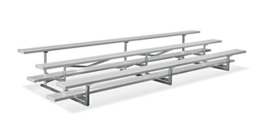
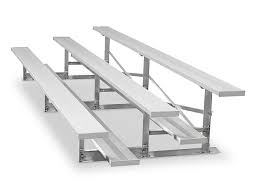
ULINE Aluminum Bleachers H-44406
TOOLS NEEDED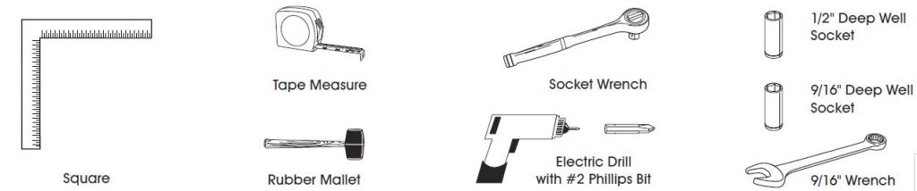
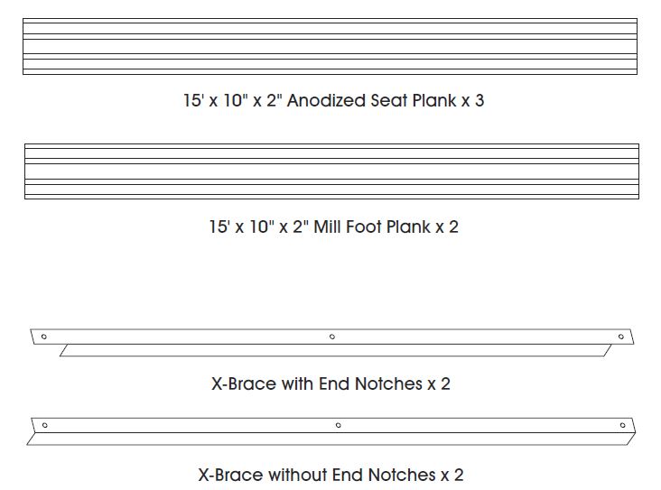
PARTS

WARNING! DO NOT ALLOW THESE ALUMINUM BLEACHER COMPONENTS TO GET WET! COMPONENTS THAT ARE BUNDLED AND GET WET WILL DISCOLOR!NOTE: If components are to be stored where they may be subjected to moisture, break bundles and separate or restack leg-to-leg so that components have no flat surfaces touching together. This will prevent chemical reaction which is unsightly, but purely cosmetic. NO CLAIMS WILL BE ALLOWED FOR SUCH ALUMINUM DISCOLORATION.CAUTION! All outdoor bleachers must be anchored to meet wind loads as specified by applicable building codes.
ASSEMBLY
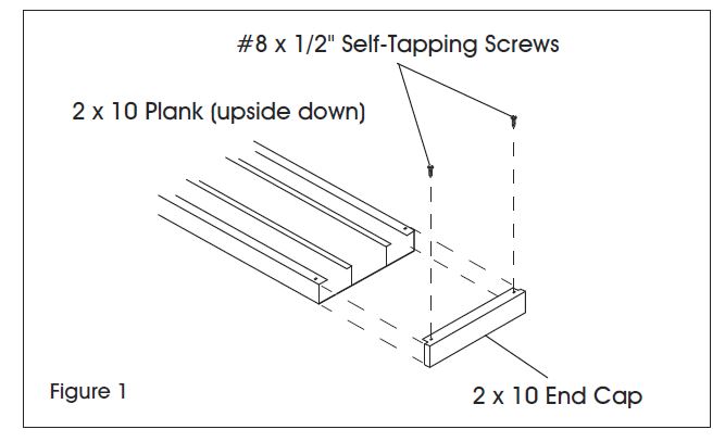
- Attach end caps to seat planks and foot planks. Make sure the pre-drilled holes on the end caps are on the underside of the planks. Use a rubber mallet to tap into place. Attach with a drill and #2 Phillips bit #8 x 1/2″ self-tapping stainless screws. (See Figure 1)

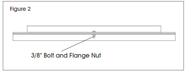
- Assemble X-braces. Use one X-brace with the notches on the ends and one X-brace without end notches. Place the pieces together flat side to flat side. Attach with a 3/8″ bolt and flange nut through the center hole. Hand tighten. Repeat for second X-brace. (See Figures 2 and 3)
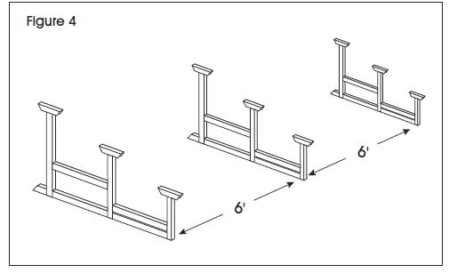
- Position frames in place, standing up, 6 feet apart. (See Figure 4)
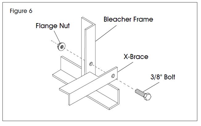
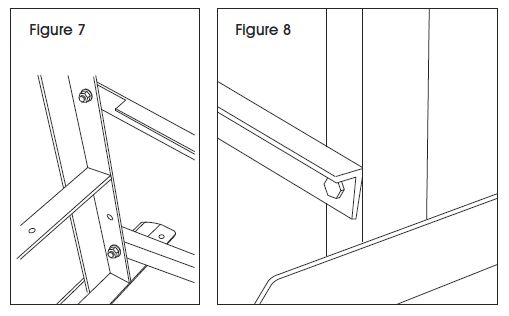
- Working from the back of the frames, attach the assembled X-brace: notched end to the third hole up from the bottom and the other end to the right frame bottom hole. Attach with 3/8″ bolts and flange nuts. Hand tighten. (See Figures 5-8)Using other end of assembled X-brace from the right frame, attach to the bottom hole and third hole up from the bottom on the middle frame. With the second assembled X-brace, attach to the middle frame using the same bottom hole and third hole up from the bottom (the brace ends overlap). Only one notched end may be on the bottom hole and one on the third hole up from the bottom. Hand tighten. (See Figure 9)Attach assembled X-brace to the left frame using the other end of assembled X-brace. Hand tighten.NOTE: Not all holes on the frame will be used.
- At this point frame is able to stand up on its own. Make sure the frame is straight, square and level. Tighten all 3/8″ bolt connections with socket wrench. (See Figure 10)
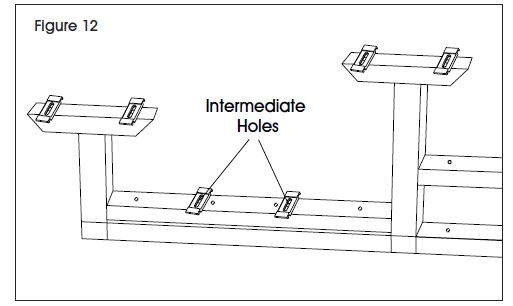
- On the frame, place a clip on each hole of the seat and foot braces. On the foot braces, use the intermediate holes. The clips should have the center indent facing up and be horizontal. Insert 5/16″ carriage bolt through each clip and frame and attach nut loosely. (See Figures 11 and 12)
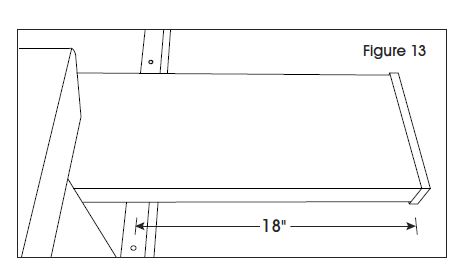
- Attach foot planks. Beginning with the bottom row, place one foot plank on top of the clips, making sure the clips rest under the plank in the outside channels. The foot plank should have an 18″ overhang on both ends, measuring from the center of the frame. Repeat for second foot plank. (See Figure 13)
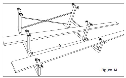
- Confirm the frame is straight and square. Center of the left foot plank frame to center of the right foot plank frame should measure 6′ on center. (See Figure 14)
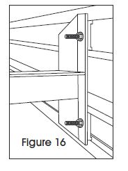
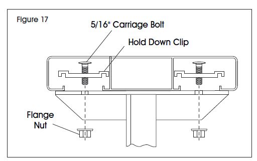
- Underneath the foot plank, turn the clips vertical so the grooves of the clip fit securely under the channel lips. Tighten the clips with flange nuts. (See Figures 15-17)
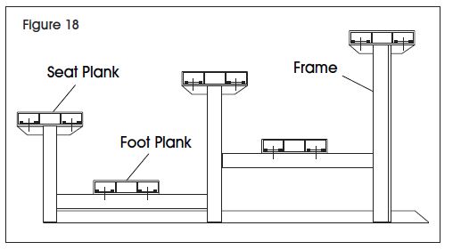
- Attach the seat planks. Starting from the top row, place one seat plank on top of the clips, making sure the clips are resting under the plank in the outside channels. (See Figure 18)
- The seat planks should have an 18″ overhang onboth ends, measuring from the center of the frame. Make sure the seat end is square with the foot planks (should line up corner to side). Repeat for the remaining seat planks. (See Figure 19)
- Tighten all clip connections with socket wrench.

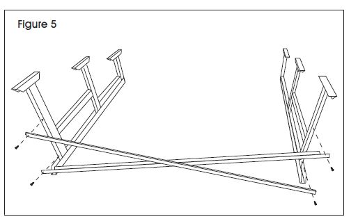
 Using other end of assembled X-brace from the right frame, attach to the bottom hole and third hole up from the bottom on the middle frame. With the second assembled X-brace, attach to the middle frame using the same bottom hole and third hole up from the bottom (the brace ends overlap). Only one notched end may be on the bottom hole and one on the third hole up from the bottom. Hand tighten. (See Figure 9)
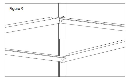 Attach assembled X-brace to the left frame using the other end of assembled X-brace. Hand tighten.NOTE: Not all holes on the frame will be used.
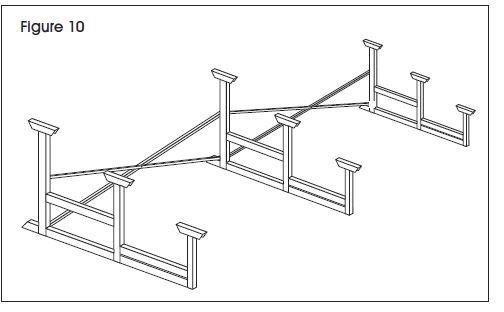

 both ends, measuring from the center of the frame. Make sure the seat end is square with the foot planks (should line up corner to side). Repeat for the remaining seat planks. (See Figure 19)
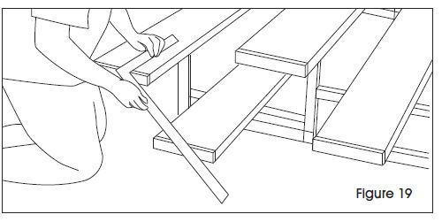
[xyz-ips snippet=”download-snippet”]