
 H-1459BAG ON A ROLL SYSTEM1-800 -295-5510uline.com
USING THIS MANUAL
READ MANUAL FIRST
![]()
IMPORTANT: Please read this manual and familiarize yourself with the equipment before use. The manual contains valuable information about the machine, its operation, and the packaging materials used with it.
SAFETY INFORMATIONThis manual contains very important information to protect both the operator and the machine. Please pay special attention to the SAFETY WARNINGS.
![]() STOP – Alerts you to dangerous situations or hazards.
STOP – Alerts you to dangerous situations or hazards.
![]() CAUTION – Alerts you to actions and situations that may affect the machine and its operation.
CAUTION – Alerts you to actions and situations that may affect the machine and its operation.
![]() NOTE – Important information about the operation and use of the machine.
NOTE – Important information about the operation and use of the machine.
 Please enter the serial number of your machine in the space provided above. If service in need, please be prepared to furnish both the model number and serial number.
UNPACK AND INSPECT
Remove all packing materials from the machine. Do not discard packing materials until you are sure there is no hidden damage. Find the manual and related hardware supplied with the machine. Carefully examine the machine for any indications of damage that may have occurred in transit.![]() NOTE: If there is any damage, contact ULINE immediately.Remember that even minor damage on the outside of the machine can cause problems with sensitive components inside the machine.
NOTE: If there is any damage, contact ULINE immediately.Remember that even minor damage on the outside of the machine can cause problems with sensitive components inside the machine.
PARTS OF THE MACHINE
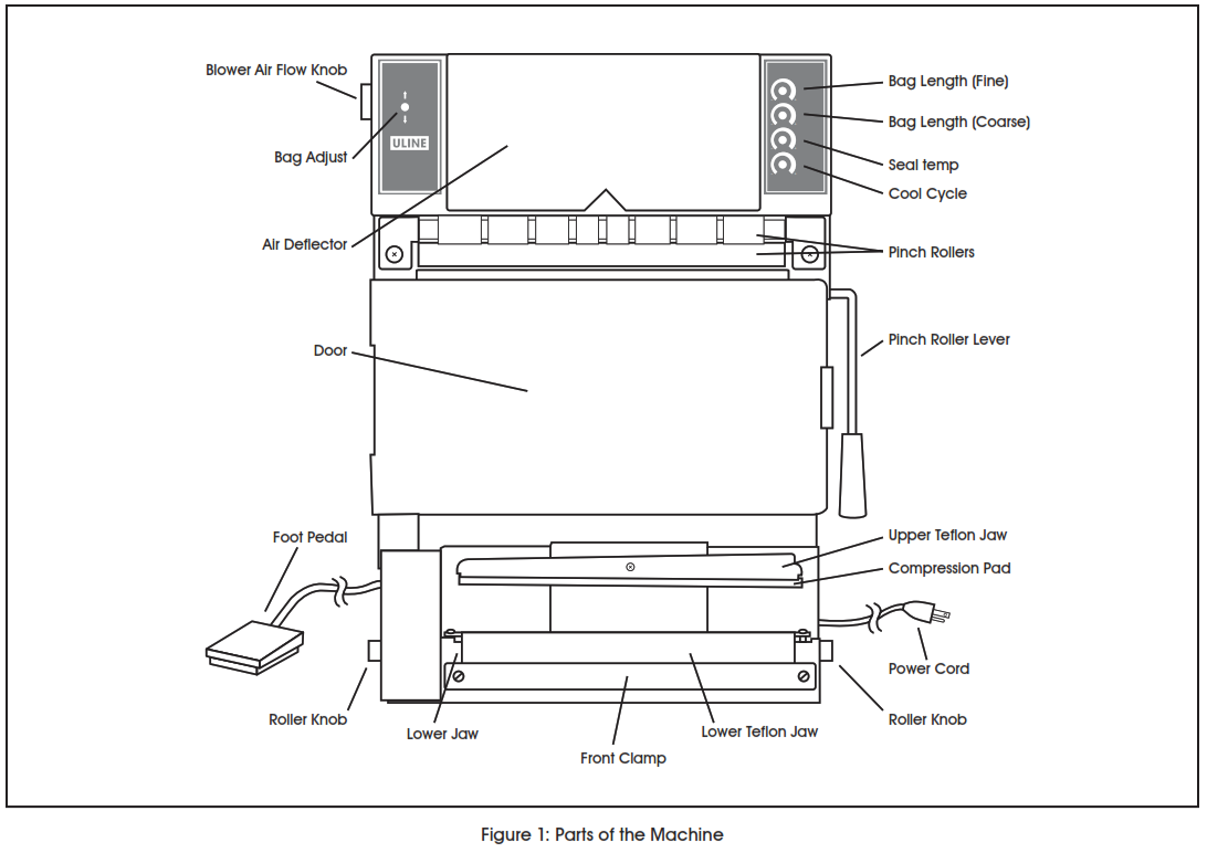
TOP LEFT FRONT PANEL:
- Bag Adjust: Flip-up or down to rewind or dispense the next bag manually.
TOP RIGHT FRONT PANEL:
- Bag Length Fine Adjustment: Clockwise for longer bags/counterclockwise for shorter bags.
- Bag Length Coarse Adjustment: Clockwise for longer bags/counterclockwise for shorter bags.
- Seal Heat-Time Adjustment for bag sealer: Clockwise to increase heating time/counterclockwise to decrease heating time.
- Cooling-Time Adjustment for bag sealer: Clockwise to increase cooling time/counterclockwise to decrease cooling time.
LOWER BACK PANEL:
- Power Switch: Push ON ( I ), push OFF ( O ).
OTHER CONTROLS:
Foot Switch: Step on to begin both the heat sealing and bag dispensing cycles.
- Blower Air Flow Knob: (Top left side) Adjusts airflow to open bags.
- Pinch Roller Lever: (Right side) Opens and closes pinch rollers.®
- Teflon Roller Adjustment Knobs: (Right and left sides) Unroll or rewind the Teflon ® cover on the lower sealing jaw assembly.
INSTALLATION
ELECTRICAL REQUIREMENTS![]() CAUTION! Follow local electrical and safety codes as well as the National Electrical Code (NEC) and the Occupational Health and Safety Act (OSHA).
CAUTION! Follow local electrical and safety codes as well as the National Electrical Code (NEC) and the Occupational Health and Safety Act (OSHA).
The machine is rated at 110 to 125 volts AC, 50/60 Hz with a ground. At this voltage, the unit draws about 5 amperes. The use of extension cords is not recommended. Locate the unit at or near an appropriate electrical supply. Be certain that the power source conforms to the machine’s requirements and that the proper gauge and type of wire is used. Make connections using the shortest possible runs of wire. Long runs of wire can result in reduced voltage.
![]() CAUTION! ALWAYS check the specifications listed on the back of the machine. It shows the correct operating voltage and amp draw for this machine.
CAUTION! ALWAYS check the specifications listed on the back of the machine. It shows the correct operating voltage and amp draw for this machine.
GROUNDINGFor your SAFETY and machine protection, DO NOT operate without a proper and secure electrical ground. If a grounded receptacle is not available, use a proper grounding adapter.
![]() NOTE: All warranties are VOID if the machine is used with an ungrounded electrical connection. Never connect a machine to any power source that exceeds the specified rating.
NOTE: All warranties are VOID if the machine is used with an ungrounded electrical connection. Never connect a machine to any power source that exceeds the specified rating.
LOCATION
![]() CAUTION! DO NOT operate this machine in explosive atmospheres. Do not subject the machine to wet or corrosive environments. Keep all flammable and caustic substances away from the machine at all times.
CAUTION! DO NOT operate this machine in explosive atmospheres. Do not subject the machine to wet or corrosive environments. Keep all flammable and caustic substances away from the machine at all times.
The unit is for indoor use only. Select a location close to where the products being packaged are stored or manufactured for best workflow. Also, consider whether the operator will sit or stand while using this machine. Place the unit on a level, sturdy table that can support the weight of the machine, the products to be packaged, and those already packaged.
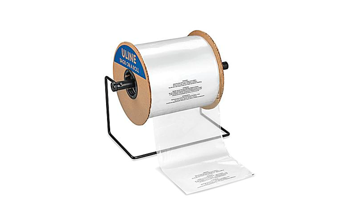
DESCRIPTION
This self-contained bag-packaging machine dispenses, opens, and seals pre-made, pre-opened bags from a roll. The chassis is 300 series stainless steel and is designed as a tabletop unit to be used in the vertical position. The machine works with pre-made, pre-opened bags on a roll-up to a maximum of 12” (30.5 cm) wide and up to 12” (30.5 cm) long. Running longer than maximum bags may require factory modifications. Heavy products may also require factory modifications.
![]() NOTE: Continuous pre-made bags-on-a-roll that are not pre-opened will not work on this machine.
NOTE: Continuous pre-made bags-on-a-roll that are not pre-opened will not work on this machine.
The Bag On A Roll Machine is extremely safe and easy to use even by inexperienced operators. There is no guesswork, and the machine is designed for the SAFETY of both your operator and your products. If the sealing jaws encounter anything significantly thicker than the bag to be sealed, no heat or pressure is applied – protects operator’s hands and fingers. The electromagnetic jaw pressure system exerts pressure only after the sealing jaws close. The adjustable sealing system provides heating and cooling time to make consistently strong heat seals. Once the heat-sealing cycle is complete, the sealing jaws reopen.
HOW THE MACHINE WORKS
- Install the pre-made, pre-opened bags on a roll in the machine.
- Close the pinch rollers.
- Set the bag length control for the proper time duration.
- Set the sealer control for the material to be sealed.
- Dispense the first bag to the filling position and the air stream blows it open.
- Place the product(s) into the open bag.
- Tear off the filled bag at the perforations.
- Hold the bag flat and place the open mouth of the bag between the open sealing jaws near the base of the machine.
- Depress the electric footswitch.
 CAUTION! DO NOT use the electric foot switch when liquids are on the floor. A dangerous electric shock might result.
 - The sealing jaws automatically close on the mouth of the filled bag.
- The automatic sealing cycle begins when the sealer jaws close fully and the next bag automatically dispenses into the air stream and opens, ready for filling.
LOADING BAGS
The front access door is located under the pinch rollers.
- Pull the handle to open the door. 1. If loading for the first time: Locate the core-roll shaft packed for shipment at the factory in the top foam end cap.)Proceed to Step 3.
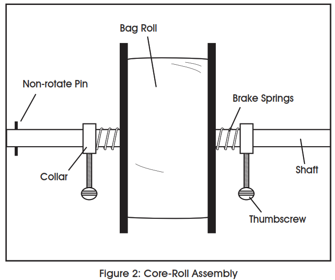
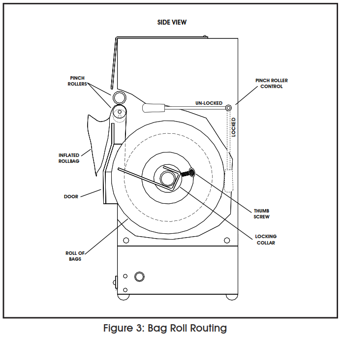
- To change rolls (See Figure 2): Remove the core-roll shaft from the holding brackets by pulling it toward you and slightly upward in one fluid motion. Note that one end of the core-roll shaft has a non-rotation pin.
- Loosen the thumbscrew on the end opposite the non-rotation pin, remove the locking collar, and one brake spring from the core shaft.
- Slide a roll of bags on the shaft so that the pre-opened parts of the bags face you.
- Reinstall the brake spring and collar and place the roll of bags and the core assembly back in the machine. Allow the core shaft to slide to the ends of the holding tracks.
- Loosen the thumbscrews on the locking collars and center the roll of bags on the core. Retighten the thumbscrews so there is slight pressure from the brake springs against the side plates on the roll of bags NOTE: If the brake springs are over-tightened, the perforations between the bags may separate while the bags are being dispensed. If the perforations break, it will require re-threading the bags through the pinch rollers. If the brake springs are too loose, the bags may unwind prematurely.
- With the roll of bags properly placed and centered in the machine, raise the lever on the right side of the machine. This releases pressure on the pinch rollers and allows easy bag threading.
- Insert the end of the first bag from the roll between the pinch rollers. Make sure bag is centered with no wrinkles. (See Figure 3)
- Pull the bag between the rollers to approximately the filling position, then lower the lever on the left side of the machine to close and lock the pinch rollers on the bag.
![]() NOTE: A blower system opens the bags for filling. This system will not work with some products such as powders, shredded paper, and other very light products. Very light products get caught in the airflow and will not go into the bag properly. Some powders may also stick to the inner surfaces of the bag in the heat seal area. This may prevent the bag from sealing properly during the heat sealing process. SET THE HEAT CONTROLS
NOTE: A blower system opens the bags for filling. This system will not work with some products such as powders, shredded paper, and other very light products. Very light products get caught in the airflow and will not go into the bag properly. Some powders may also stick to the inner surfaces of the bag in the heat seal area. This may prevent the bag from sealing properly during the heat sealing process. SET THE HEAT CONTROLS
SET THE HEAT CONTROLS
The machine includes one heating element mounted to the lower jaw of the heat sealer and one spare, taped inside the front access door. The heating elements make a Ribbon Seal approximately 12″ (30.5 cm) long by 1/8” (3 mm)The heat sealer has an adjustable heat-time control that may be set from 0% to 100%.
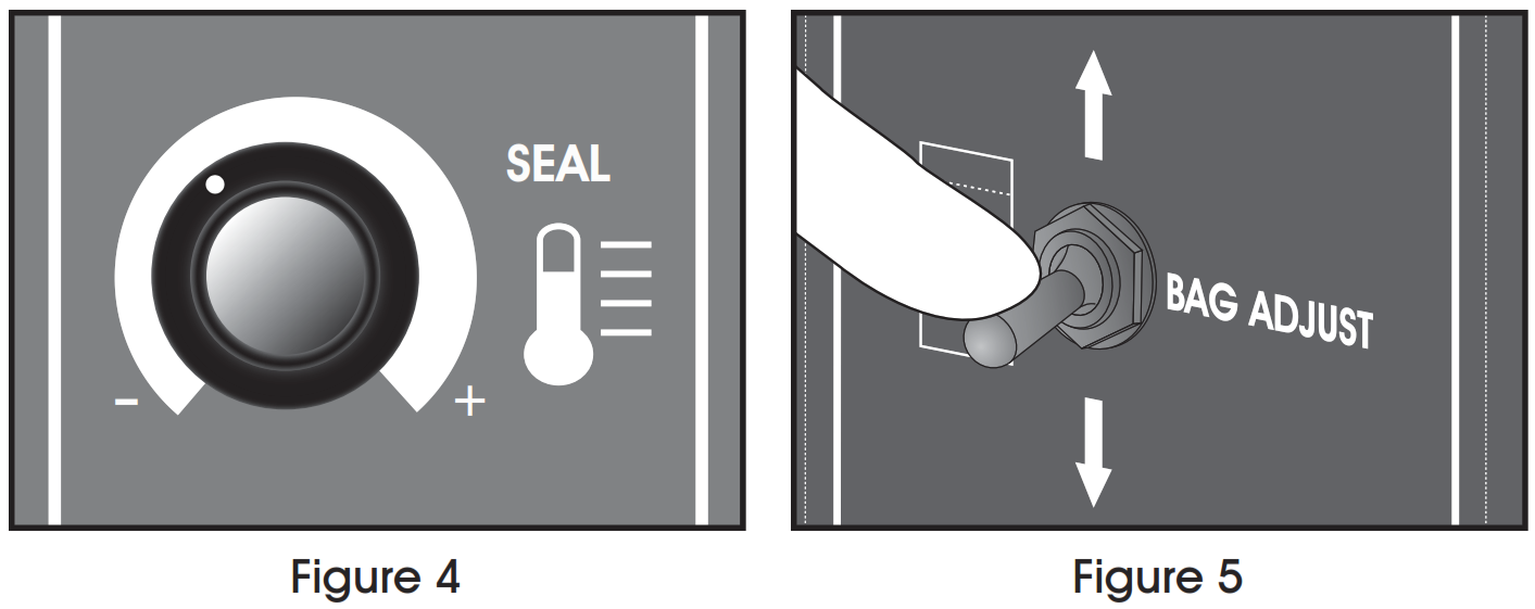
- Set the HEAT SEALING control to indicate approximately 30%. (See Figure 4)
- Flip the BAG ADJUST switch to dispense a bag. (See Figure 5)
- Tear the bag off along perforation, then position the mouth of the bag between the seal jaws.CAUTION! NEVER attempt to heat seal through the printed area on a bag, as it will cause sticking and gumming.
- Depress the footswitch until the sealing cycle starts, then release. When the sealing cycle is complete, remove the bag from the Teflon® covered lower sealer jaw using a left to right or right to left peeling motion.
INSPECTING THE HEAT SEALAn acceptable ribbon seal shows the grain of the Teflon® jaw covers and has a slightly milky appearance. An acceptable trim seal leaves a fine raised bead at the end of the bag – no fringe or angel hair.
IF THE HEAT SEAL IS TOO WEAKIncrease the heat-time setting slightly (clockwise): If the heat seal does not look complete or if the bag will not stay closed, repeat the process using another bag until you are satisfied with the results. Be sure that the seal area is not coated with a contaminant.
IF THE HEAT SEAL MELTS THROUGHDecrease the heat-time setting slightly (counterclockwise): If the seal melts through, too much of the bag material extrudes away during sealing, the top of the bag flops back on itself, or if the sealed ends look shrunken. Repeat testing using another bag until you are satisfied.
![]() NOTE: Use as little heat time as possible to obtain the necessary results. Overheating weakens the seal area on the bag and causes higher maintenance. The heating element expands and contracts during each sealing cycle, eventually causing the element to wear out. When replacing the element, it may be necessary to readjust the temperature control timer.
NOTE: Use as little heat time as possible to obtain the necessary results. Overheating weakens the seal area on the bag and causes higher maintenance. The heating element expands and contracts during each sealing cycle, eventually causing the element to wear out. When replacing the element, it may be necessary to readjust the temperature control timer.
RESIDUAL HEAT – HEAT BUILD-UPThe machine is designed to allow sufficient time for the heating element and sealing compression pad to cool during the bag dispensing and filling period. It is not intended for use as a high-speed heat sealer. Attempting to operate the sealer at speeds beyond its intended use causes residual heat build-up resulting in bag seal stretch and melt-through and require early replacement of the heating element, Teflon® covers, and compression pad.
BAG STOP POSITION ADJUSTMENTSIf the bag in the staging area opens properly, fill it, tear it off, and heat seal it. The next bag dispenses during the heat-sealing cycle. If the bag does not stop in the correct position, follow the instructions below. This is trial-and-error; when using bags of different lengths, write down the proper settings as you determine them. The settings will vary slightly from one machine to another. Initial set-ups may take a few minutes.
IF THE BAG STOPS TOO LOW ON THE MACHINE
- Decrease the BAG LENGTH setting slightly (counterclockwise). Use the coarse or fine adjusting control as needed.
- Flip the BAG ADJUSTMENT switch up or down until the next bag is in position for filling.
- Fill, tear off, and heat-seal the bag.
- Repeat until the next bag stops in the proper position each time.
IF THE BAG STOPS TOO HIGH ON THE MACHINE
- Increase the BAG LENGTH setting slightly (clockwise). Use the coarse or fine adjusting control as needed.
- Flip the BAG ADJUSTMENT switch up or down until the next bag is in position for filling.
- Fill, tear off, and heat-seal the bag.
- Repeat until the next bag stops in the proper position each time.
MAINTENANCE
![]() If you encounter any problems with the Uline Bag on a Roll System, contact Uline Customer Service at 1-800-295-5510.
If you encounter any problems with the Uline Bag on a Roll System, contact Uline Customer Service at 1-800-295-5510.
TEFLON®JAW COVERS
Both the upper and lower jaws of the heat sealer are covered with Teflon® glass cloth to aid heat sealing and prevent sticking. Since the heat source is in the lower jaw it is exposed to greater abuse and is, therefore, larger and easily repositioned.
REPLACE UPPER JAW COVERReplace the upper Teflon® cover if it becomes torn, burned, or the sealed bag sticks to it. It is held in place by a spring and is easily replaceable.
REPOSITION LOWER JAW COVER®The lower Teflon cover provides an easily repositionable sealing surface. The cover is anchored at one end to a roller held in place by two screws; the other end passes through a clamp-type retainer on the face of the machine.To reposition the lower Teflon® cover:
- Loosen the two plastic screws holding the clamp.
- Using either one or both of the knobs located on the sides of the machine, rotate the roller slightly so that a new seal area is positioned over the heating element.(See Figure 6)Figure 6: Repositioning lower Teflon® cover
- After repositioning, retighten the clamp using the same two plastic screws.
- Tear off the used Teflon® material below the clamp. Replace the roll when there is no more usable Teflon®
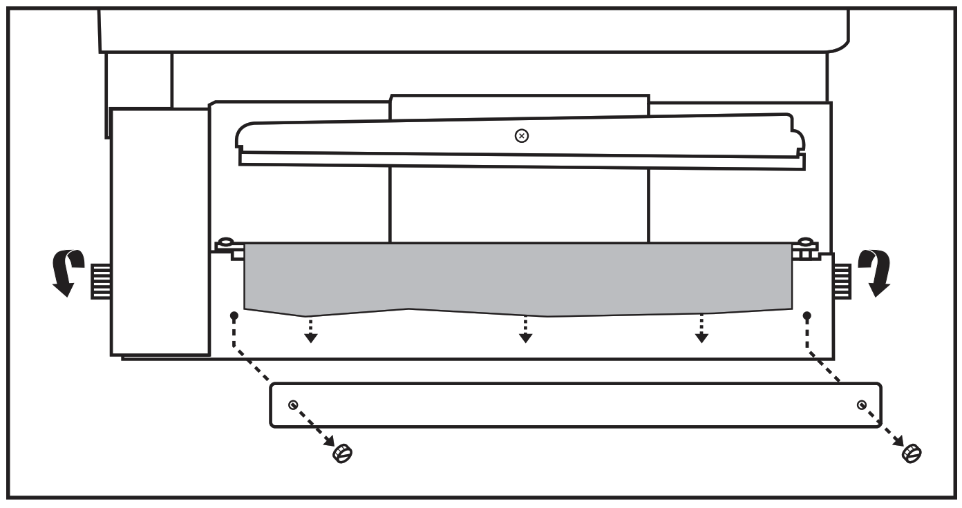 Figure 6: Repositioning lower Teflon® cover
![]() CAUTION! Never attempt to make heat seals without the lower Teflon® cover over the heating element and lower sealing jaw.
CAUTION! Never attempt to make heat seals without the lower Teflon® cover over the heating element and lower sealing jaw.
REPLACING THE LOWER TEFLON® COVER
To replace the lower Teflon® cover roll: (See Figure 7)
- Loosen the two plastic clamp screws and rotate the roller knob with one hand while pulling the trailing end of the Teflon® up with the other until the two roller mounting screws are visible.Figure 7: Replacing lower Teflon® cover
- Remove the two screws (use either a magnetic or starter screwdriver). Keep the screws for reuse in mounting the new Teflon® cover roll.
- Install the new Teflon® cover roll bypassing the mounting screws through the two eyelets and into the roller. The screws should be snug. Do not overtighten as damage could result.
- Rotate the roller knob, winding the Teflon ® cover onto the roller. Insert the free end behind the clamp. To reduce waste, put as little Teflon ® beyond the end of the clamp as possible.
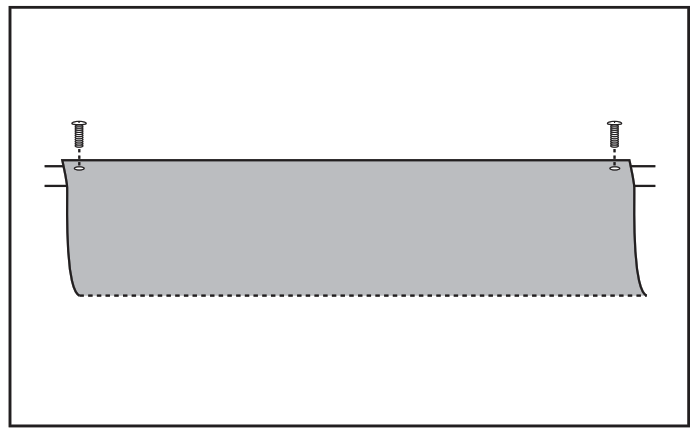 Figure 7: Replacing lower Teflon® cover
REPLACING COMPRESSION PAD
Over time the silicone rubber compression pad becomes brittle and pitted and needs to be replaced.
- Remove the upper Teflon® cover by first removing the retaining spring. Keep the parts for reuse.
- Remove the nut and bolt retaining the compression pad holder. (See Figure 8)
- Peel off the old compression pad and clean the area so it’s free of lumps and old adhesive.
- The replacement compression pad has a pressure-sensitive backing. Carefully remove the backing paper and attach the new compression pad to the jaw. Be sure that it is flat and has no depressions or lumps.
- Reinstall the upper compression pad holder and Teflon® cover.

HEATING ELEMENT REPLACEMENT
The heating element expands and contracts during each sealing cycle and will eventually break over time. Replace using only Uline heating elements.
![]() Make sure that the machine is turned off and the power cord is secured before working on the machine.
Make sure that the machine is turned off and the power cord is secured before working on the machine.
![]() Any attempt to use elements designed for use on another machine or in another application may not work properly and may cause damage and/or create a dangerous situation. Use of non-Uline parts will void all warranties.
Any attempt to use elements designed for use on another machine or in another application may not work properly and may cause damage and/or create a dangerous situation. Use of non-Uline parts will void all warranties.
- Loosen the two clamp mounting screws and rotate the roller knobs to rewind the Teflon® onto the roller to expose the heating element. (See Figure 9)
- Remove the heating element retaining nuts at each end of the element (keep for reuse).
- Remove the old heating element and discard.
- Inspect the insulator on the lower jaw for signs of cracks, pits, burn marks, etc.
- If the insulation material is worn replace it before installing the new heating element. Remove the old insulator when necessary, clean the area, apply a smooth coating of RTV adhesive, install the replacement insulation and allow it to dry for several hours before installing the new heating element.
![]() NOTE: The heating element has a top and a bottom. See Figure 9 for proper positioning and installation.
NOTE: The heating element has a top and a bottom. See Figure 9 for proper positioning and installation.
![]() NOTE: The seal jaw assembly is spring-loaded on the left end, fixed on the right end. HEATING ELEMENT INSTALLATION
NOTE: The seal jaw assembly is spring-loaded on the left end, fixed on the right end. HEATING ELEMENT INSTALLATION
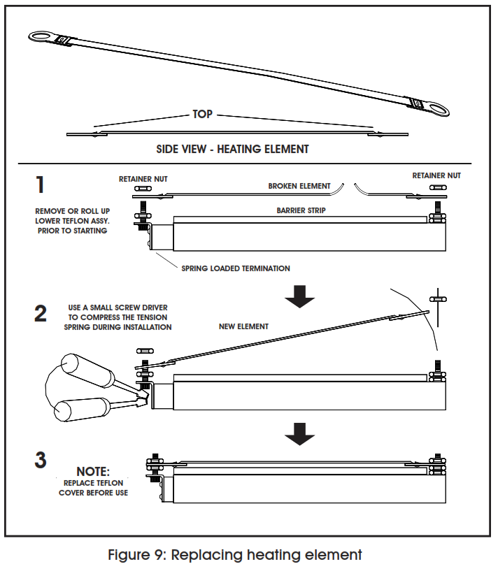
6. Place the left end of the new heating element over the threaded post at the left end of the jaw assembly.7. Compress the left end of the jaw (spring-loaded) and place the right end of the heating element over the fixed threaded post on the right end.8. Make sure that the heating element is positioned correctly, is not twisted, and lays flat against the lower jaw.9. Reinstall the retainer nuts no more than finger-tight.10. Reinstall the lower Teflon® cover.
1-800-295-5510uline.com
[xyz-ips snippet=”download-snippet”]