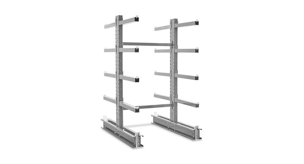
![]() CANTILEVER RACKS1-800-295-5510uline.com
CANTILEVER RACKS1-800-295-5510uline.com

TOOLS NEEDED

Wrenches: 3/4″, 15/16″, 1%”
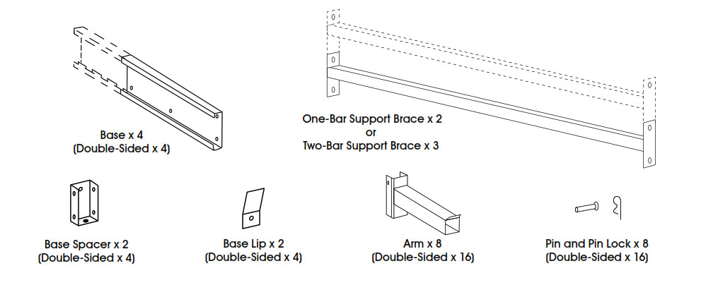
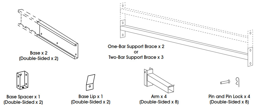
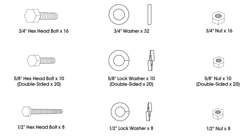
STARTER UNIT PARTS LIST
 |
 |
 |
ASSEMBLY INSTRUCTIONS FOR STARTER UNIT
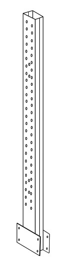
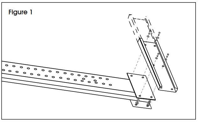
1. Lay the column flat on the floor. Attach the base to the column using 3/4″ hex head bolts, 3/4″ washers, and 3/4″ nuts as shown. (See Figure 1)
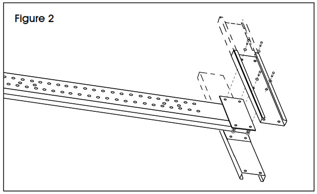
2. Flip the column to the other side. Attach the other base to the column using 3/4″ hex head bolts, 3/4″ washers, and 3/4″ nuts as shown. (See Figure 2)![]() NOTE: Don’t tighten the bolts for this base all the way.
NOTE: Don’t tighten the bolts for this base all the way.
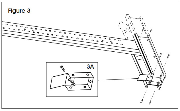
3. Attach the base lip to the base spacer using a 5/8″ hex head bolt, 5/8″ lock washer, and 5/8″ nut. (See Figure 3A). Slide the base spacer between the bases, align the holes and attach using 5/8″ hex head bolts, 5/8″ lock washers and 5/8″ nuts. (See Figure 3)![]() NOTE: If constructing a double-sided unit, attach 1 base spacer at each end of the base.
NOTE: If constructing a double-sided unit, attach 1 base spacer at each end of the base.
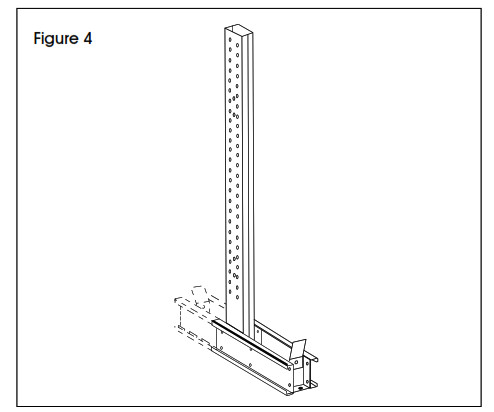
4. Tighten down all bolts on the base. Now lift the constructed column to the upright position. (See Figure 4)
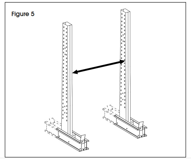
5. Repeat Steps 1-4 to construct the other base and column. Align the second constructed column at the appropriate distance from the first constructed column in order to attach the support braces. (See Figure 5)
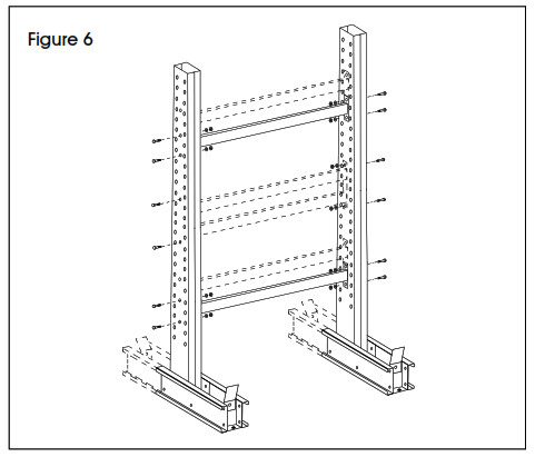
6. Attach the lower support brace to the constructed columns first using 1/2″ hex head bolts, 1/2″ lock washers, and 1/2″ nuts. Then attach the remaining support brace or braces to the constructed columns. (See Figure 6) c:5-7![]() NOTE: Use caution when attaching the first support brace to avoid tipping the constructed columns.
NOTE: Use caution when attaching the first support brace to avoid tipping the constructed columns.
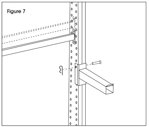
7. Attach the arms in the desired location using the pin and pin lock. Arms adjust in 3″ increments. (See Figure 7)
ADD-ON UNIT PARTS LIST
 |
 |
 |
ASSEMBLY INSTRUCTIONS FOR ADD-ON UNIT.
1. Repeat steps 1-4 from the Starter Unit Instructions to build the base and column. Align the constructed column at the appropriate distance from the Starter Unit in order to attach the support braces. (See Figure 8)

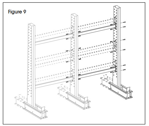
2. Attach the support braces to the Starter Unit using 1/2″ hex head bolts, 1/2″ lock washers and 1/2″ nuts. (See Figure 9)![]() NOTE: In order to attach support braces to Starter Unit, remove 1/2″ hex head bolts, 1/2″ lock washers and 1/2″ nuts from the end of the Starter Unit closest to the Add-On Unit. Reattach bolts, washers and nuts through both Starter Unit and Add-On Unit support braces.
NOTE: In order to attach support braces to Starter Unit, remove 1/2″ hex head bolts, 1/2″ lock washers and 1/2″ nuts from the end of the Starter Unit closest to the Add-On Unit. Reattach bolts, washers and nuts through both Starter Unit and Add-On Unit support braces.
3. Attach the arms in the desired location using the pin and pin lock. Arms adjust in 3″ increments. (See Figure 10)

[xyz-ips snippet=”download-snippet”]