ULINE Deluxe Workstations
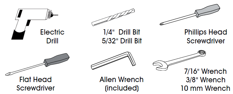
TOOLS NEEDED
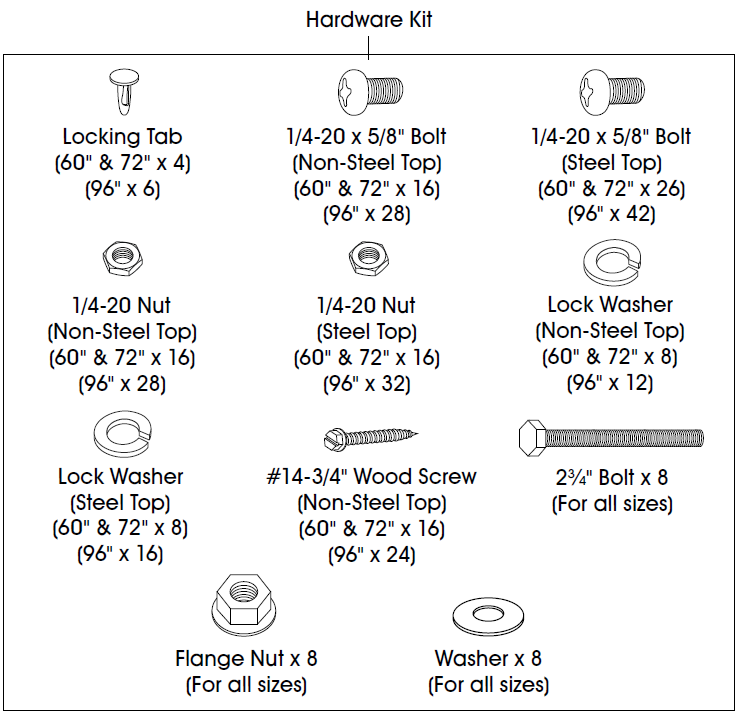
PARTS
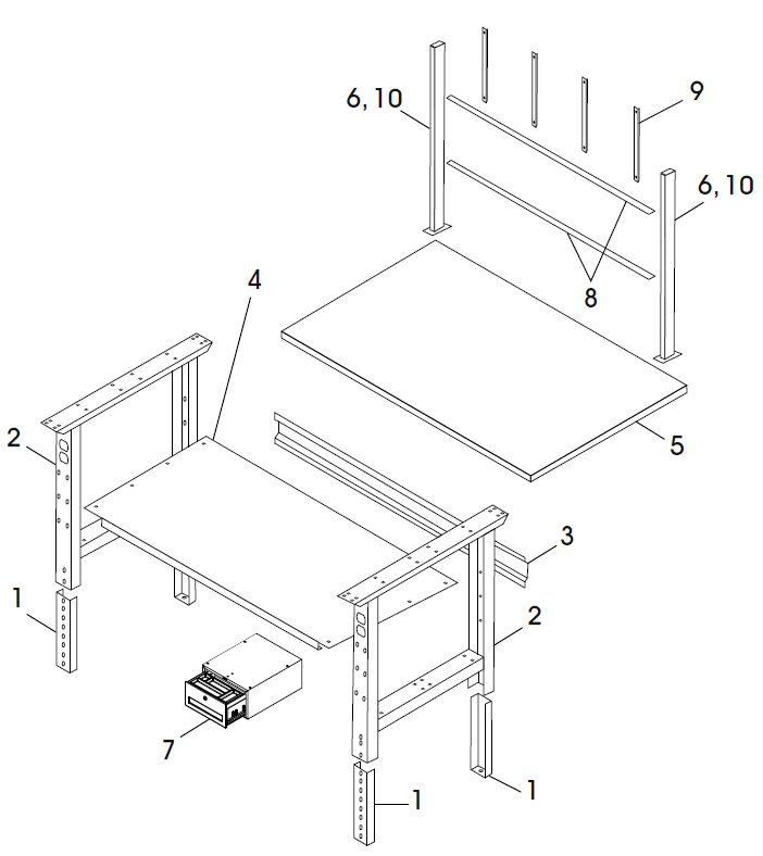
WARNING: If purchased a packing station, please use the instructions packaged with the lower shelf.CAUTION! Some parts may have sharp edges. Care must be taken when handling various pieces to avoid injury. For your safety, wear a pair of work gloves when assembling.
| # | DESCRIPTION | 60″ AND 72″ QTY. | 96″ QTY. |
| 1 | Adjustable Foot | 4 | 6 |
| 2 | Leg | 2 | 3 |
| 3 | Stringer | 1 | 1 |
| 4 | Lower Shelf | 1 | 1 |
| 5 | Tabletop | 1 | 1 |
| 6 | Upright | 2 | 2 |
| 7 | Drawer | 1 | 1 |
| 8 | Panel Mounting Bar* | 2 | 2 |
| 9 | Panel Bracket* | 6 | 8 |
| 10 | Upright with Cobalt Drill Bit** | 2 | 2 |
For use with optional louvered and pegboard panels.
ASSEMBLY
LEGS AND FRAME ASSEMBLY
- Insert adjustable feet (1) into legs (2) and slide into place at desired height.NOTE: If desired, insert locking tabs through legs and adjustable feet to lock feet into place.
- Place legs (2) in upright position. Legs should be placed approximately 53″ apart for 60″ workstations and 65″ apart for 72″ workstations. The 96″ workstations use three legs that should be placed 45″ apart.
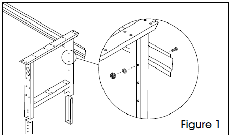
- Attach stringer (3) to legs using center holes in back of legs. Fasten using eight 1/4-20 x 5/8″ bolts, lock washers and nuts (12 bolts, lock washers and nuts for the 96″ workstation), but do not fully tighten. (See Figure 1)

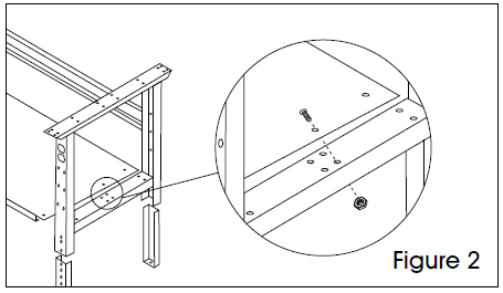
- Place lower shelf (4) across braces of legs. Attach lower shelf using eight 1/4-20 x 5/8″ bolts and nuts (16 bolts and nuts for the 96″ workstation). Now, fully fasten hardware placed in step 3. (See Figure 2)
- To attach tabletop (5) to frame assembly, place tabletop on a smooth, non-marring surface with top side facing down.
- Rotate assembled frame upside down and line up with pre-drilled pilot holes on the bottom side of tabletop.
WOOD, LAMINATE, ESD, STAINLESS STEEL TOP ASSEMBLY
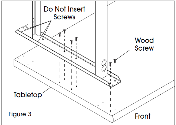
- Using six wood screws, attach leg to underside of tabletop (5) through pre-drilled pilot holes. Only insert screws into the front and center pre-drilled pilot holes. Holes in the back should not be used at this time. (See Figure 3)FOR 96″ WORKSTATIONS ONLY: For the center leg only, insert two additional wood screws into the pre-drilled pilot holes at the back of the table.
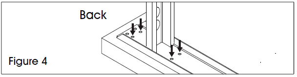
- Using a 1/4″ drill bit, drill four holes all the way through tabletop in the pre-drilled pilot hole locations shown in Figure 3. They should line up with the holes in the back of the leg. (See Figure 4)NOTE: Use cobalt drill bit supplied with uprights for stainless steel tops. This bit is specifically designed to drill through stainless steel material.NOTE: These holes are drilled to allow mounting of uprights in later steps.FOR 96″ WORKSTATIONS ONLY: Step 2 only applies to the two ends of the table. The center leg is already fully assembled.
- Repeat steps 1 and 2 with other leg(s).
STEEL TOP ASSEMBLY
Align leg holes to end of tabletop. Secure with six 1/4″-20 x 5/8″ bolts per leg. Threaded inserts are provided on each tabletop end. (See Figure 5)FOR 96″ WORKSTATIONS ONLY: For the center leg only, align leg with two holes in center of tabletop on each end and secure with four 1/4-20 x 5/8″ bolts, 1/4-20 nuts and lock washer.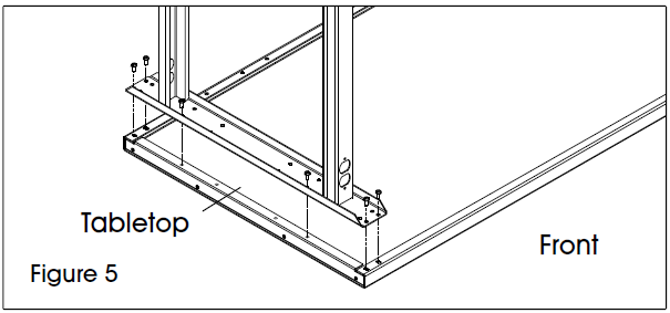
DRAWER ASSEMBLY
| # | DESCRIPTION | QTY. |
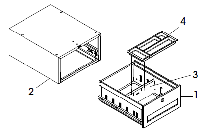
| 1 | Drawer | 1 |
| 2 | Drawer Housing | 1 |
| 3 | Divider | 1 |
| 4 | Plastic Tray | 1 |
| Keys (Not Shown) | 2 | |
| Hardware packet (Not Shown) | 1 |
NOTE: Drawer comes pre-assembled.NOTE: The drawer and suspension have a 70 lb. weight capacity.
ATTACHING TO NON-STEEL TOP
- To free drawer (1) from housing (2), fully extend the drawer from the housing. Flip one plastic tab on the sliding rails up and the second plastic tab on the sliding rails down.
- Using housing as template, mark location of four holes for wood screws onto underside of tabletop. (Recommendation: 1/2″ offset from front of tabletop).
- Using 5/32″ drill bit, drill holes into tabletop, drilling about 1/2″ to 3/4″ deep.
- Secure housing to underside of top, using four #14-3/4″ hex head slotted wood screws.
- Insert drawer into housing.
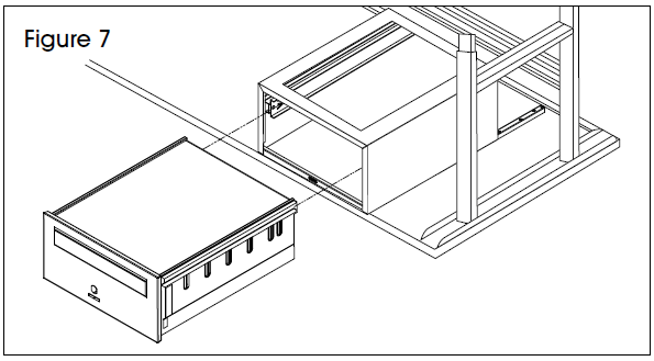
ATTACHING TO STEEL TOPNOTE: Mounting channels are included with the steel top. (See Figure 6) Channels may extend past the drawer assembly.
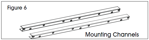
- On the underside of the table, slide mounting channels front to back into table flanges. When channels are aligned, mounting holes should be approximately 14½” apart. Secure each channel with two 1/4″-20 x 5/8″ bolts. (See Figure 7)
- To free drawer (1) from housing (2), fully extend the drawer from the housing. Flip one plastic tab on the sliding rails up and the second plastic tab on the sliding rails down.
- Attach the drawer assembly to the mounting channels using four 1/4″-20 x 1/2″ bolts. (See Figure 7)
- Close the drawer.
ATTACHING MULTIPLE DRAWER UNITS
- To free drawer (1) from housing (2), fully extend the drawer from the housing. Flip one plastic tab on the sliding rails up and the second plastic tab on the sliding rails down.
- Bolt housing together with four 1/4-20 bolts and nuts.
- Insert drawer into housing.
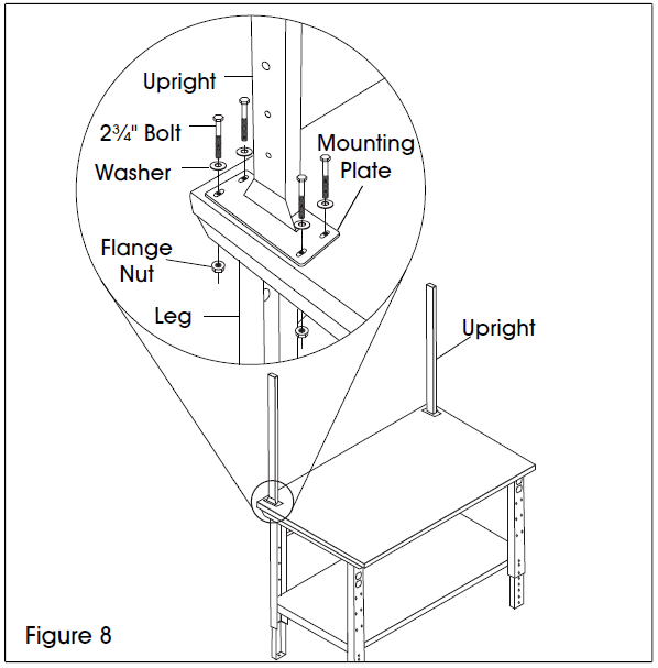
UPRIGHT ASSEMBLY
- Carefully set table upright and recheck all nuts, bolts and screws for tightness.
- Position upright (6) on back corner of the tabletop. The mounting plate should be positioned directly over the previously drilled holes. Fasten four 2″ bolts and washers through uprights, tabletop and legs using 10 mm wrench. Secure with flange nuts on underside of table. (See FigureNOTE: Steel tops already come with drilled holes through top.
- Repeat with other upright. (See Figure 8)
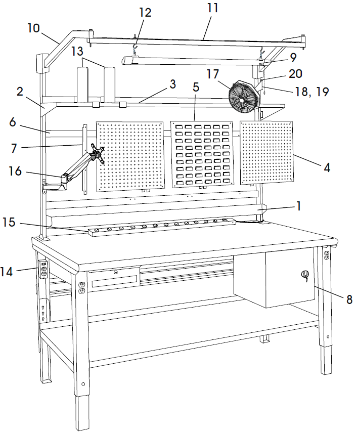
OPTIONAL ACCESSORIES
CUSTOMIZE YOUR WORKSTATION:
NOTE: The following products are optional accessories. Mounting hardware is included with each accessory.
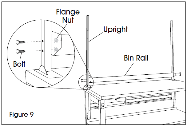
BIN RAIL ASSEMBLY
- Line up bin rail (1) with uprights at desired height.
- Secure to uprights with four 1⁄” bolts and flange nuts. (See Figure 9)
| # | DESCRIPTION | QTY. |
| 1 | Bin Rail | 1 |
| 2 | Shelf Bracket | 2 |
| 3 | Shelf | 1 |
| 4 | Pegboard Panel | 2 |
| 5 | Louvered Panel | 1 |
| 6 | Panel Mounting Bar | 2 |
| 7 | Panel Bracket | 6 |
| 8 | Cabinet | 1 |
| 9 | LED Shop Light | 1 |
| 10 | Light Bracket | 2 |
| 11 | Light Steel Beam | 1 ▲ |
| 12 | “S” Hooks | * |
| 13 | Shelf Divider | * |
| 14 | Leg Outlet | * |
| 15 | Tabletop Power Strip | 1 |
| 16 | Monitor Arm | 1 |
| 17 | Fan | 1 |
| 18 | 6″ Fan Mounting Bracket | 1 |
| 19 | 10″ Fan Mounting Bracket | 1 |
| 20 | Fan Upright Mounting Bracket | 1 |
SHELF ASSEMBLY
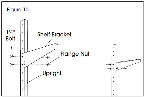
- Line up shelf brackets (2) with uprights at desired height.
- Secure to uprights with four 1⁄” bolts and flange nuts. (See Figure 10)
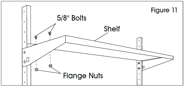
- Place shelf (3) on brackets. Install to brackets with four 5/8″ bolts and flange nuts. (See Figure 11)
PEGBOARD AND LOUVERED PANEL ASSEMBLY
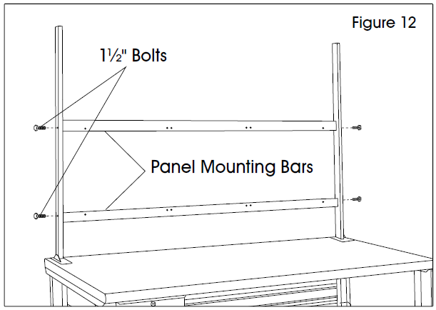
- Position panel mounting bars (6) at desired height on the uprights. There should be 8 open holes on the upright between the top and bottom bar to allow for panel mounting. Secure bars to upright with four 1″ bolts. (See Figure 12)NOTE: The holes on the face of the mounting bars should be facing the inside direction.
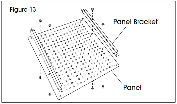
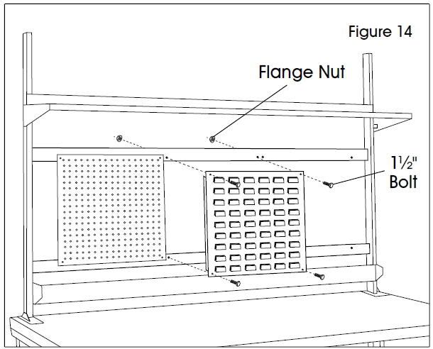
- Attach panel brackets (7) to pegboard panel (4) or louvered panel (5). Line up holes on bracket with the four holes on the ends of the panels. Attach four 5/8″ bolts and flange nuts on the center holes only. (See Figure 13)
- Install panels (4 and/or 5) to the mounting bars (6). Line up holes on the top and bottom of the panel with the holes in the bar. Secure using four 1⁄” bolts and flange nuts. (See Figure 14)
- Repeat for additional panels. The 48″ workstation holds up to 2 panels, 60″ and 72″ workstations hold up to 3 panels, and the 96″ workstation holds up to 4 panels.
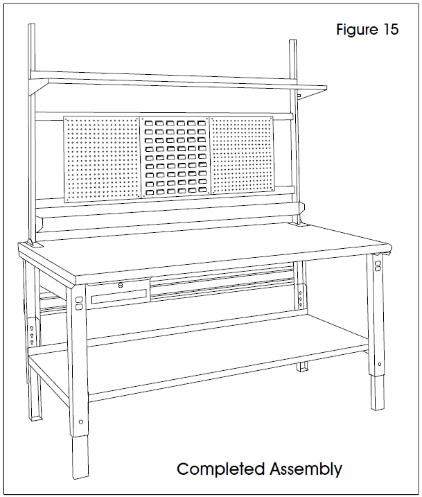
- Assembly is complete. (See Figure 15)
CABINET ASSEMBLY
NOTE: The cabinet and suspension have a 70 lb. weight capacity.1. Open the cabinet (8) door. Using a 7/16″ wrench and Phillips screwdriver, remove adjustable shelf by unscrewing 4 screws.
ATTACHING TO NON-STEEL TOP
- Using cabinet as a template, mark location of four holes for wood screws onto underside of tabletop. (Recommendation: 1/2″ offset from front of table top).
- Using 5/32″ drill bit, drill holes into table top, drilling about 1/2″ to 3/4″ deep.
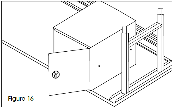
- Secure cabinet to underside of top, using four #14-3/4″ hex slotted wood screws. (See Figure 16)
- Reinstall adjustable shelf and close cabinet door.
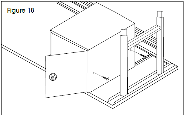
ATTACHING TO STEEL TOPNOTE: Mounting channels are included with the steel top. (See Figure 17) Channels may extend past the cabinet assembly.
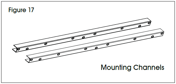
- On the underside of the table, slide mounting channels front to back into table flanges. When channels are aligned, mounting holes should be approximately 14⁄” apart. Secure each channel with two 14⁄”-20 x 5/8″ bolts.
- Attach the cabinet to the mounting channels using four 14⁄”-20 x 1/2″ bolts. (See Figure 18)NOTE: Cabinet door can be flipped to have right or left facing door.
- Close the cabinet door and turn the workstation right side up. Reinstall adjustable shelf.
LIGHT KIT ASSEMBLY
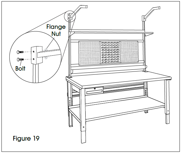
- Line up light brackets (10) with uprights at desired height.
- Secure to uprights with four 2″ bolts and flange nuts. (See Figure 19)
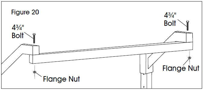
- Place light steel beam (11) at desired depth underneath brackets. Fasten to brackets (10) with two 4¾” bolts and flange nuts. (See Figure 20)NOTE: 48″ light kit does not include steel beam. Skip to 4b.
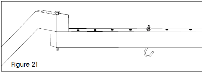
- a For 60, 72 and 96″ Light Kits: Place two “S” hooks (12) at desired mounting points along the steel beam and secure with two flange nuts. (See Figure 21)4. b For 48″ Light Kits: Place two “S” hooks (12) at desired depth underneath bracket. Fasten to brackets (10) with two flange nuts. (See Figure 22)
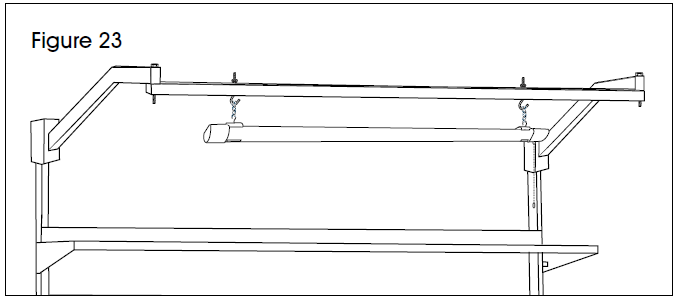
- Attach hanging chains to LED shop light (9) and mount to “S” hooks. (See Figure 23)
 4. b For 48″ Light Kits: Place two “S” hooks (12) at desired depth underneath bracket. Fasten to brackets (10) with two flange nuts. (See Figure 22)
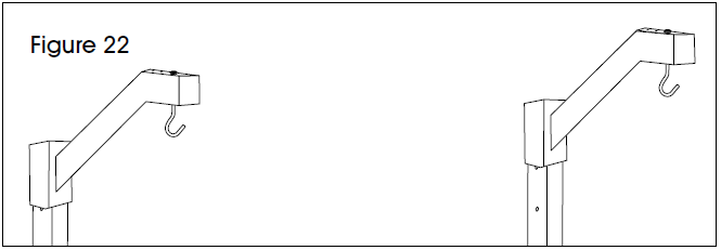
SHELF DIVIDER ASSEMBLY
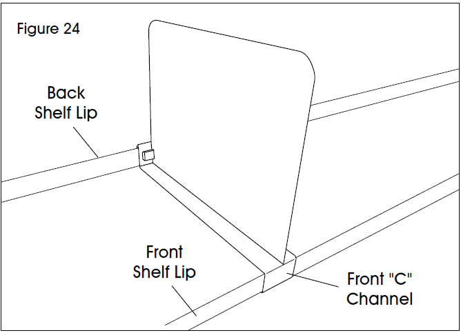
- Line up front “C” channel of divider (13) with front lip of top shelf. Insert divider into front lip at angle. Once in place, allow divider to drop and magnetize to back shelf lip. (See Figure 24)
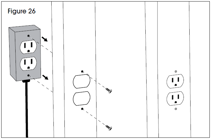
LEG OUTLET ASSEMBLY
NOTE: Mounting hardware comes pre-installed in outlet.
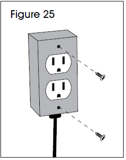
- Remove top and bottom screws from outside facing oval outlets. (See Figure 25)
- Insert outlet (14) into workbench leg cut outs with the oval outlets facing the outside of the leg assembly. Secure to leg assembly with the two screws removed in step one. (See Figure 26)
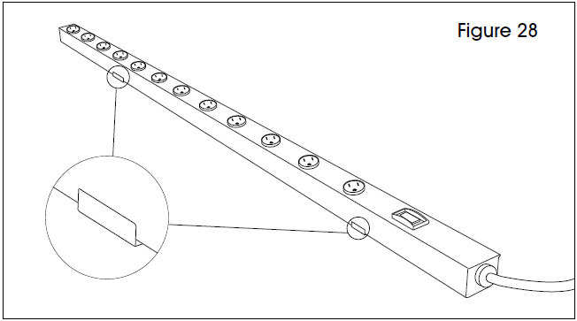
TABLETOP POWER STRIP ASSEMBLY
- Choose desired location for power strip. Place two supplied mounting clips roughly 32″ apart (clip side up). Using an electric drill, fasten to tabletop with two supplied wood screws. (See Figure 27)
- Secure power strip (15) by snapping into the mounting clips. (See Figure 28)

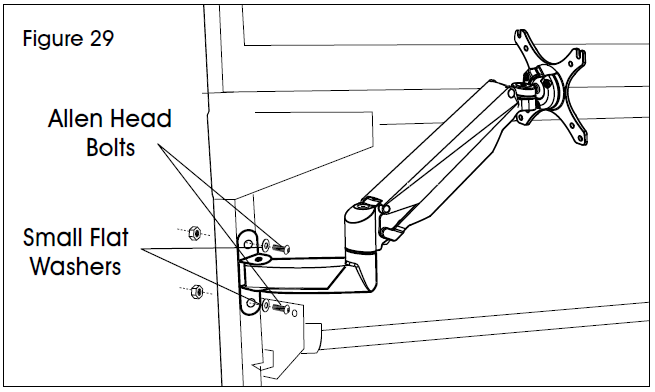
MONITOR ARM ASSEMBLY
- Line up monitor arm mounting bracket (16) with uprights at desired height.
- Secure to uprights with two M6 x 35 mm or M6 x 50 mm Allen head bolts, two small flat washers and two hex nuts using an Allen wrench and 10 mm wrench. (See Figure 29)
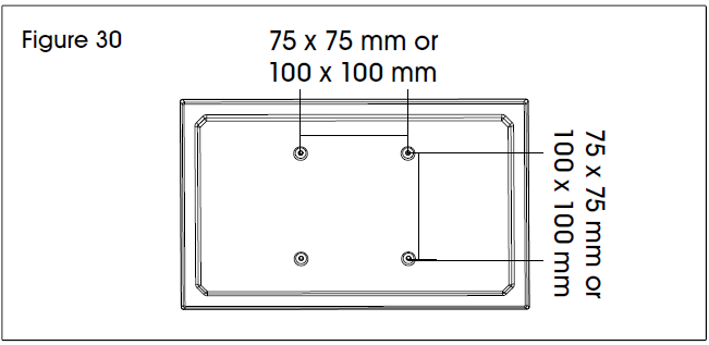
ATTACHING MONITOR
NOTE: Make sure monitor has a VESA hole pattern of 100 x 100 mm or 75 x 75 mm. (See Figure 30)NOTE: If monitor is attached to a fixed base, remove monitor from base.CAUTION! Be careful not to scratch screen during installation.
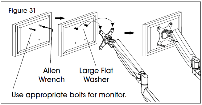
- Easy-adjust monitor mount includes a built-in counterweight system for free-range motion. Arm in mount may need to be adjusted to allow monitor to stop at desired position. Attach monitor to plate. (See Figure 31)
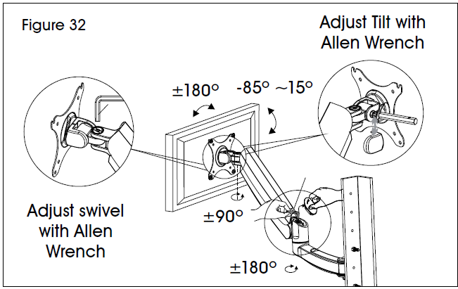
- To adjust the counterweight, use 5 x 5 Allen wrench on screw above middle joint. Turn towards “–” if monitor raises up. Turn towards “+” if monitor lowers. Adjust until mount can be stopped at desired position. (See Figure 32)
CABLE MANAGEMENT
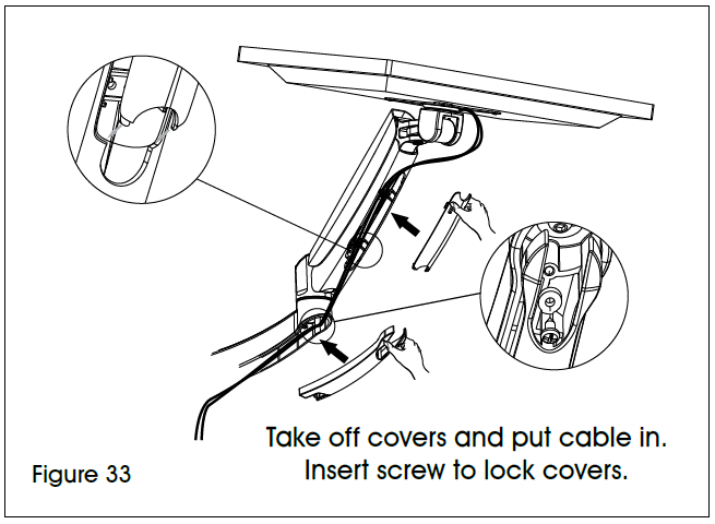
- To remove covers, use a Phillips head screwdriver to unscrew the two screws securing covers to the monitor arm. This allows user to slide cables through covers. Once complete, re-secure the covers to the monitor arm using the Phillips head screws. (See Figure 33)
FAN ASSEMBLY
NOTE: Fan comes with 6″ and 10″ long bracket. Choose desired bracket based on application.
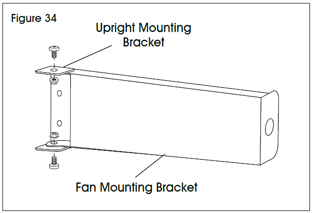
- Slot 6″ or 10″ fan mounting bracket between opening in fan upright mounting bracket. Align holes of each bracket and attach using two M6 x 12 mm hex bolts and two M6 flange nuts. (See Figure 34)
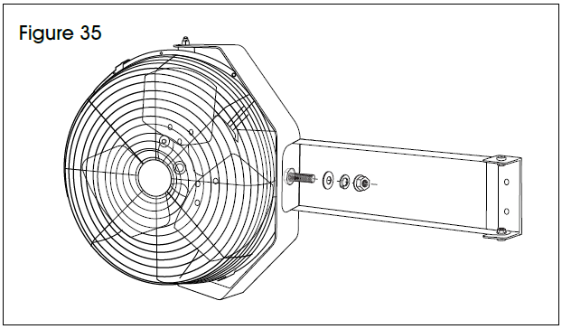
- Align hole on the opposite end of fan mounting bracket to the hole on the crescent fan bracket. Attach using M12 x 20 mm hex bolt, M12 washer, M12 lock washer and M12 hex nut. (See Figure 35)
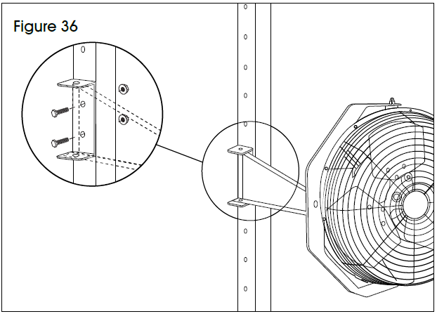
- Align fan assembly with uprights at desired height.
- Secure to uprights with two M6 x 40 mm hex bolts and two M6 flange nuts. (See Figure 36)
![]()
[xyz-ips snippet=”download-snippet”]