
ULINE Edge-Lit Aceylic Exit Sign
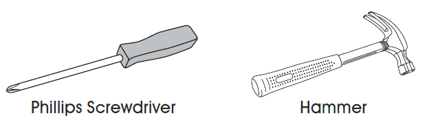
TOOLS NEEDED
SAFETY
CAUTION! When using electrical equipment, basic safety precautions should always be followed, including:
- Do not use outdoors.
- Do not mount near gas or electric heaters.
- Do not let power cords touch hot surfaces.
- Use caution when servicing batteries. Avoid possible shorting.
- Equipment should be mounted in locations and at heights where it will not readily be subjected to tampering by unauthorized personnel.
- The use of accessories not recommended by manufacturer may cause unsafe conditions.
- Do not use this equipment for anything other than intended use.
- Before wiring to AC service, turn off AC power at fuse or circuit breaker.
- Disconnect AC power and unplug battery before servicing.
- Only use specified lamps in the fixture.
- Battery in this unit may not be fully charged. After AC service is supplied to unit, let battery charge for at least 24 hours before performing any tests.
INSTALLATION
CHOOSE PLATE
- If using a single-sided application against a wall, use clear panel with EXIT on one side.
- If using a single-sided application not against a wall, use mirrored panel with EXIT on one side.
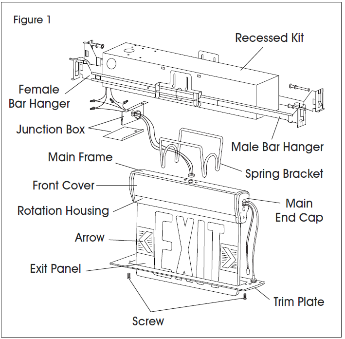
- If using a double-sided application, use mirrored panel with EXIT on both sides. (See Figure 1)
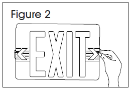
DIRECTIONAL ARROWS
- Determine if directional arrows are needed. (See Figure 2)
- If arrow(s) is needed, remove only the instruction film.
- If arrow(s) is not needed, remove the arrow and instruction film together.
ELECTRICAL CONNECTIONS
NOTE: If using 120VAC, connect black and white leads to building utility. (See Figure 3)NOTE: If using 277VAC, connect orange and white leads to building utility. (See Figure 4)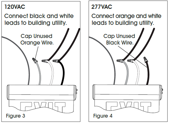
Cap off all unused wires. In all cases, use standard wire nuts to connect wires.
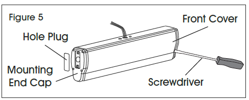
RECESSED CEILING MOUNTING
NOTE: Turn off electricity first.
- Use screwdriver to open the front cover and connect the battery connector. (See Figure 5)
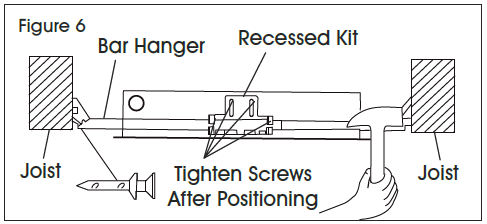
- Position recessed kits and bar hangers between joists. (See Figure 6)NOTE: Make sure bar hangers are hung in the correct position.
- Temporarily position recessed kits by hammering nail-in tabs on bar hangers. Once completed, secure permanently with nails.NOTE: Bar hangers should be level with bottom of joists.
- Adjust height of recessed kits vertically using adjusting slots. Tighten all screws on adjusting slots and bar hanger bracket to secure adjusting bracket and bar hangers.
- Make proper electrical connections at junction box in the metal box or at junction box in the ceiling of building. (See Figure 7)NOTE: If using 120VAC, connect black and white leads to building utility. (See Figure 3)NOTE: If using 277VAC, connect orange and white leads to building utility. (See Figure 4)
- Connect test switch and LED indicator cables via connectors.
- Secure trim plate by using provided screws. (See Figure 8)
- Gently insert EXIT panel into main body assembly. NOTE: If EXIT panel is for single face, ensure EXIT letter direction is correct.NOTE: The unit can be installed on any surface. EXIT panel can rotate to any angle from 0-180º.
 NOTE: Make sure bar hangers are hung in the correct position.
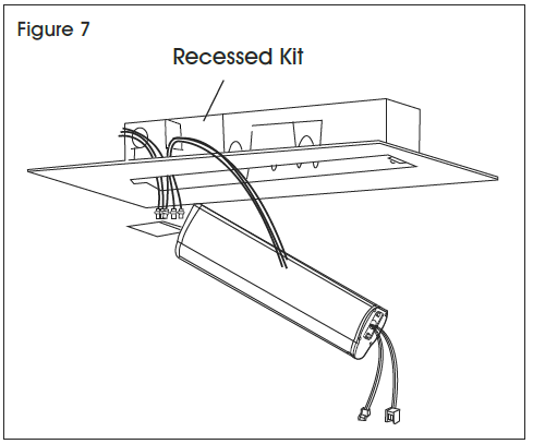 NOTE: If using 120VAC, connect black and white leads to building utility. (See Figure 3)NOTE: If using 277VAC, connect orange and white leads to building utility. (See Figure 4)
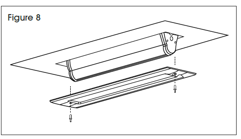
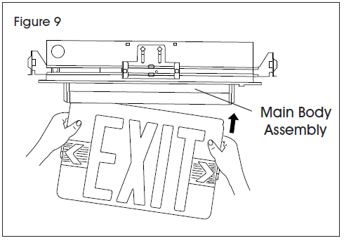 NOTE: If EXIT panel is for single face, ensure EXIT letter direction is correct.NOTE: The unit can be installed on any surface. EXIT panel can rotate to any angle from 0-180º.
RECESSED WALL MOUNTING
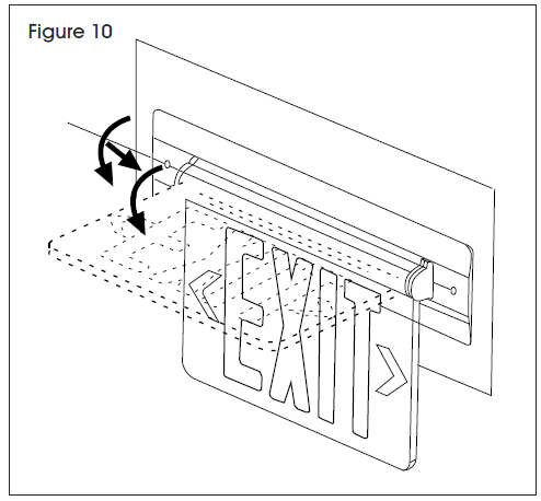
- Refer to steps 1-8 in Recessed Ceiling Mounting.NOTE: Recessed ceiling mounting can be rotated 90º to become recessed wall mounting. (See Figure 10)
[xyz-ips snippet=”download-snippet”]