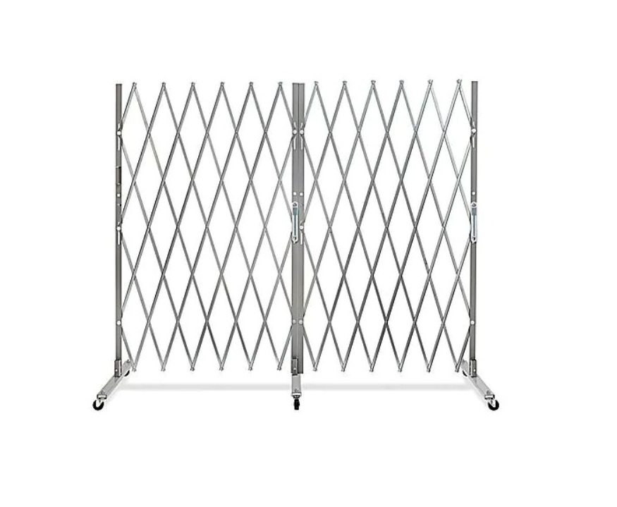
ULINE Fixed Single Folding Security Gate Installation Guide
TOOLS NEEDED
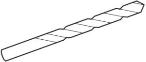
- 3/4″ Masonry Drill Bit

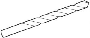
- 1/4″ Masonry or Wood Drill Bit
PARTS NEEDED
- 5/16 x 2″ Long Lag Bolt
Masonry Door Frame or Wall Installations (Wall Installations may require lead anchors)
PARTS INCLUDED
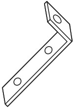
- 2″ Standard “L” Bracket
- Bearing Washer
- Locking Bar

INSTALLATION
- Before installing, decide on gate “L” bracket that forms top hinge allows gate placement in the recess of door frame. Installation can also be made outside or inside of wall next to door or opening frame. (See Figure 1)
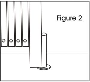
- Have a helper extend the gate and stand it upright where it will be mounted. Drill 3/4″ diameter x 3″ deep hole, 1¼” from wall into the floor for gate pin to set into. Place a bearing washer over floor hole and set bottom gate pin into floor mount hole. (See Figure 2) CAUTION! Check to confirm gate will swing away from opening when not in use. This will provide a clear opening for normal traffic.
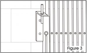
- Extend gate and hang “L” bracket on top of gate to verify where it will be To release tension you may lift the wheel 1/2″-3/4″ off the floor. Mark and drill pilot holes into door frame or wall. It may be easier to drill pilot holes if you remove the gate from it’s floor mount. Place bearing washer and bottom gate pin back into floor mount. Slip “L” bracket over top of gate and bolt (not included.) (See Figure 3)
- Wood door frames or walls: 5/16 x 2″ lag bolts.
- Steel door frames or walls: Drill and tap for 5/16 x 2″ lag bolts.
- Brick or concrete frames or walls: 5/16 x 2″ Lag bolts set into 3/8″ holes with lead anchors.
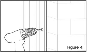
- Extend and retract gate to its stops to work out stiffness, then fully extend gate across Align padlock holes and position the locking bar on door frame or wall. Mark and drill pilot holes. Secure with 5/16 x 2″ lag bolts. (See Figure 4)
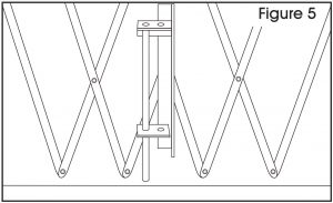
- Only gates 7′ and wider include a center drop pin. If included, fully extend gate across opening and mark the floor where center drop pin is located. Drill a 3/4″ diameter x 3″ deep hole into the concrete floor. Lower center drop pin. (See Figure 5)
- Gate can be secured to locking bar using padlock. Open gates slowly at first to avoid warping.

Contact Us
Phone: 1-800-295-5510Web: uline.com

[xyz-ips snippet=”download-snippet”]