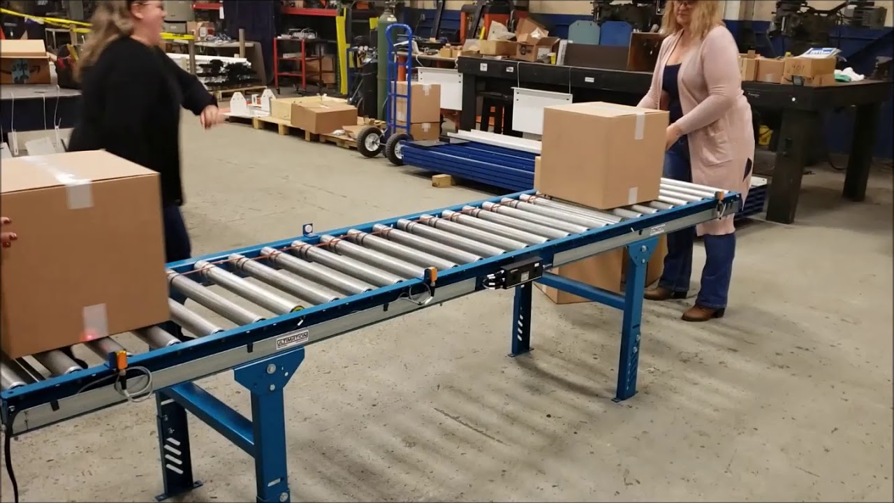
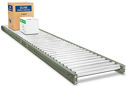
ULINE Gravity Roller Conveyors 1.9″ Diameter Rollers
ASSEMBLY INSTRUCTIONS
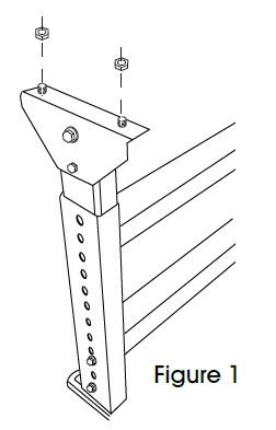
BOLTING CONVEYOR FRAME(S) TO H-STAND LEG SUPPORTS
NOTE: H-Stands are sold separately.Hardware included: 4 hex head bolts, 4 flange nuts.
- Hardware is pre-screwed into the tops of the H-Stands. Remove the hardware. (See Figure 1)

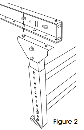
- Bolting two H-Stands to one conveyor frame: PositionH- Stands on the end of the conveyor frame, lining up with two holes on the end. Fasten bolts through conveyor and H-Stand.(See Figure 2)
Bolting a single H-Stand to two conveyor frames: Position the H-Stand halfway between the end of two conveyor frames, lining up one hole on each conveyor with the H-Stand.Fasten bolts through conveyors and H-Stand. (See Figure 3)
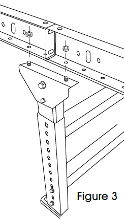
NOTE: Each conveyor frame includes mounting holes for an optional center leg support. Adding a third support increases weight capacity.
BOLTING MULTIPLE CONVEYOR FRAMES TOGETHER
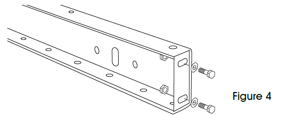
NOTE: Hardware included: 4 hex head bolts, 4 flange nuts and 4 washers.
- Hardware is pre-screwed into the ends of the conveyor frame. Remove the hardware.(See Figure 4)
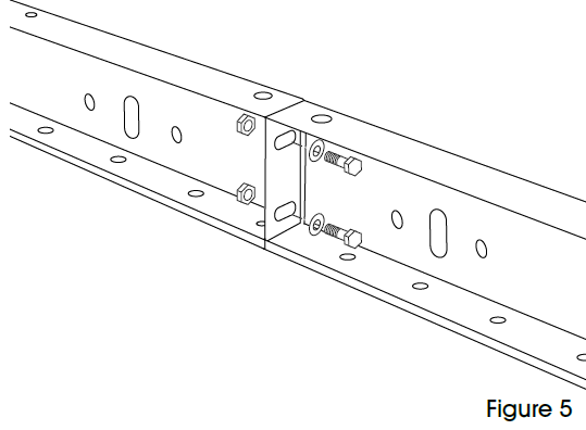
- Fasten the bolts through the ends of both conveyor frames, using the same holes that they arrived in.(See Figure 5)
![]()
[xyz-ips snippet=”download-snippet”]