
H-1119 Take-A-Number System
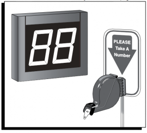
H-1119TAKE-A-NUMBER SYSTEM
1-800-295-5510uline.com
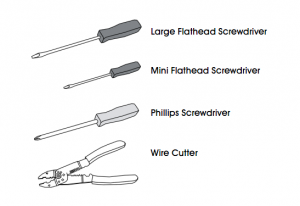
TOOLS NEEDED
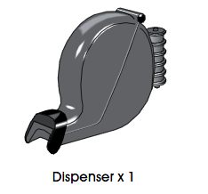
PARTS LIST
COUNT PIECES BEFORE ASSEMBLING
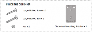
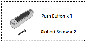
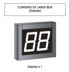
CONTENTS OF SMALL BOX (Dispenser)
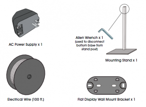
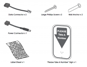
CONTENTS OF LARGE RECLOSABLE BAG (Stand and Wiring)
OPERATION AND USE OF DISPENSER
OPERATION
- Customer takes a number from the dispenser and waits until the number appears on the display.
- Press the (+) push button once to display the next number.
- Press and hold the (+) push button to advance the numbers by tens.
- Use the () push button to go back one number at a time.
NUMBER DISPENSER
Number dispenser can be mounted to either the wall or stand.
WALL MOUNTING
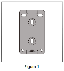
- Mark mounting holes on wall using dispenser mounting bracket as a template. (See Figure 1)
- Drill holes using 3/16″ to 5/16″ drill bit.
- Use wall anchors (not included) if attaching to surfaces other than solid wood.

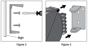
- Position dispenser mounting bracket (longer holder at the top) over holes in wall and fasten with two slotted screws. (See Figure 2)
- Snap dispenser into bracket. (See Figure 3)
NOTE: For permanent mounting, use the base of stand as a template, mark and drill four holes and secure base of stand to surface with four screws (not included).2. Align holes in dispenser mounting bracket (longer holder on top) with holes in post. Push two large slotted bolts through bracket and sign and secure with nuts. (See Figure 4)3. Snap dispenser into bracket. (See Figure 3)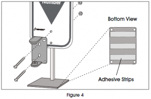
LOADING DISPENSER
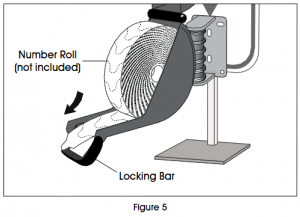
- Pull down locking bar to open dispenser.
- Drop in number roll (not included) so the numbers roll out from the bottom. (See Figure 5)Number Roll (not included)
STAND MOUNTING
1. Position mounting stand in the desired location on countertop.
NOTE: For clean, smooth surfaces, remove backing from adhesive strips on the base of the stand and secure to surface.
Locking Bar Figure 53. Pull end of roll through end of dispenser. Close dispenser and snap locking bar back into place.
DISPLAY MOUNTING AND INSTALLATION
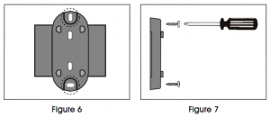
ELECTRONIC DISPLAYMOUNTING BRACKET TO WALL1. Determine where to place the display so it is easily seen by customers.2. Mark mounting holes on wall using the flat display wall mount bracket as a template. (See Figure 6)3. Drill holes using 5/16″ drill bit.4. Use wall anchors (included) if attaching to surfaces other than solid wood.5. Position flat display wall mount bracket over drilled holes and fasten with two large Phillips screws. (See Figure 7)
WARNING! Electrical Shock Hazard Do not connect display to power until all push button and power connections are complete. Serious electrical shock, injury or death may result.
The Take-A-Number System includes three push buttons. Set two push buttons to advance numbers and one to go back to a previous number.
- Cut a length of electrical wire to reach from each push button location to display.
- Strip wire ends about 1/2″. (See Figure 8)
- On the underside of one push button: Loosen screws. Wrap one wire end around one screw post and wrap the other wire end around the other screw post. Tighten the screws to secure wires. (See Figure 9)
- Secure push buttons to surface using the two included slotted screws. (Optional)
- Repeat steps 13 with the two remaining push buttons.
1. Strip wire ends about 1/2″ for all three push buttons. (See Figure 8)2. Each data connector has three numbered ports. Loosen screws on ports 2 and 3 with a mini flathead screwdriver.3. For (+) push buttons: Twist the same color wires together from two of the push buttons (copper to copper, silver to silver). Insert the twisted wires into ports 2 and 3 on one data connector. Tighten screws to secure wires. (See Figure 10)4. For () push button: Use the wire from one remaining push button. Insert the wires into ports 2 and 3 on the second data connector. Tighten screws to secure wires. (See Figure 10)
PLUGGING DATA CONNECTORS INTO DISPLAY
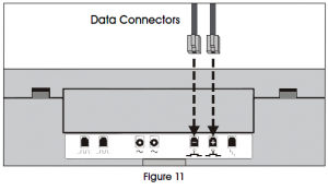
1. Plug the data connector with two push buttons attached into the (+) jack on the back of the display. (See Figure 11)2. Plug the other data connector with the single push button attached into the () jack on the back of the display. (See Figure 11)
DISPLAY MOUNTING AND INSTALLATION CONTINUED
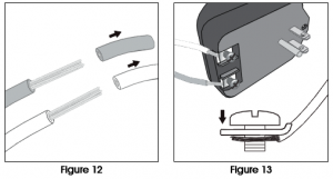
PLUGGING DATA CONNECTOR INTO DISPLAY (CONTINUED)3. Mark which push button is plugged into the (+) and () jacks:(+) Push button advances the numbers.() Push button goes back to previous numbers.WIRING AC POWER SUPPLYWARNING! Do not connect display to power until all push button and power connections are complete. Serious electrical shock, injury or death may result.1. Cut a length of electrical wire that will reach from the electrical outlet to the display location.2. Strip wire ends about 1/2″. (See Figure 12)3. Loosen both screws on the bottom of the AC power supply.4. Attach one wire to each screw post underneath the metal plates. Tighten screws to secure wires. (See Figure 13)
WIRING AC POWER SUPPLY TO POWER CONNECTOR
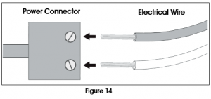
1. The power connector has two ports. Loosen both small screws using the mini flathead screwdriver.2. Insert one wire end into each port. Tighten screws to secure wires. (See Figure 14)
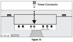
3. Plug the power connector into either of the two power receptacles located on the back of the display. (See Figure 15)4. Plug the AC power supply into the nearest outlet.SETUPSETTING SOUND TONE AND VOLUME
 SETUPSETTING SOUND TONE AND VOLUME
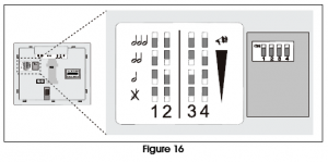
Use a mini screwdriver to change the tone and volume switches on back of the display. (See Figure 16) Set the sound tone with switches 1-2:
- No sound: 1-OFF, 2-OFF
- Single tone: 1-OFF, 2-ON
- Double tone: 1-ON, 2-OFF
- Triple tone: 1-ON, 2-ON Set the volume with switches 3-4:
- Low volume: 3-OFF, 4-OFF
- Medium volume: 3-ON, 4-OFF (recommended in most cases)
- High volume: 3-OFF, 4-ON
- Highest volume: 3-ON, 4-ON
DISPLAY MOUNTING AND INSTALLATION CONTINUED
DISPLAY START-UPThe display shows a number of messages on start-up once it is plugged in.Display shows:· Program version: “P-“, then number· TOM-Net address: ‘ad”, then 51 or 21· Last number displayed when power was disconnected: Number, (“00″ if first-time start-up.)· Error message if display is set as a duplicate master: ‘ed”
OPTIONAL DISPLAY SETUP (See Figure 17)To enter setup options, make sure display is unplugged. Hold down one of the (+) push buttons and plug the display back in. Release the push button when display shows “UP.”Set display update delay:· Display shows “UP” followed by the current delay time in seconds, (ex. “00”). Press the (+) button to increase the delay one second at a time.· After three seconds without pushing the button, the set display sleep time appears.Set display sleep time:· Display shows “SL” followed by the current setting in minutes. (The display shuts off after a set period of time with no button pushes.) Press the (+) button to increase the delay before the indicator goes into sleep mode one minute at a time.· After three seconds without pushing the button, the display flashes and the number change appears.
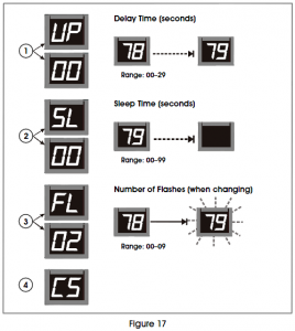 Set display flashes when number changes: · Display shows “FL” followed by the current setting showing number of flashes. Press the (+) button to increase the number of times the display will flash when the number changes one flash at a time. · After three seconds without pushing the button, the display shows “CS” and saves new settings to memory.
INSTALLING ADDITIONAL INDICATORS· See instructions included with H-2769 or H-4665.
1-800-295-5510uline.com
[xyz-ips snippet=”download-snippet”]