![]()
H-1663 PLASTIC EXIT SIGN1-800-295-5510uline.com
TOOLS NEEDED

SAFETY
CAUTION! When using electrical equipment, basic safety precautions should always be followed, including:
- Do not use outdoors.
- Do not mount near gas or electric heaters.
- Do not let power cords touch hot surfaces.
- Use caution when servicing batteries. Avoid possible shorting.
- Equipment should be mounted in locations and at heights where it will not readily be subjected to tampering by unauthorized personnel.
- The use of accessories not recommended by the manufacturer may cause an unsafe condition.
- Do not use this equipment for anything other than intended use.
- Before wiring to AC service, turn off AC power at fuse or circuit breaker.
- Disconnect AC power and unplug the battery before servicing.
- Only use specified lamps in the fixture.
- The battery in this unit may not be fully charged. After the AC service is supplied to the unit, let the battery charge for at least 24 hours before performing any tests.
INSTALLATION
BACK MOUNTING
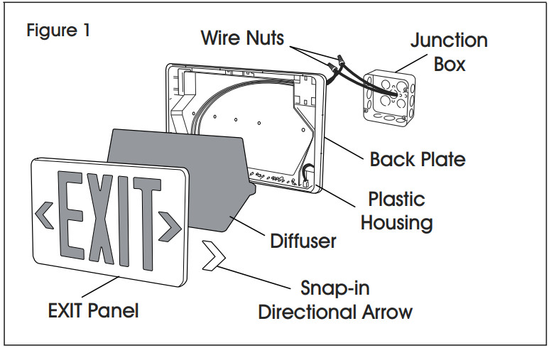
- Drill 1/4″ holes into oblong knockouts on backplate that correspond to junction box holes to be used. (See Figure 1)

- Feed the transformer input leads through the center hole and make the proper connections. If using 120VAC, connect the black and white leads to the building utility. If using 277VAC, connect the orange and white leads to the building utility. Cap off the unused wire. If the unit is self-powered, be sure to snap the battery connector together.
- Feed the excess wire into the junction box and secure the backplate to the junction box. (See Figure 1)
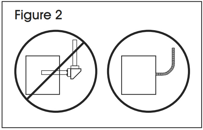
- Snap-in arrows on EXIT panel as required. Then snap EXIT panel to housing: top first, then the bottom. (See Figure 1) NOTE: Use flexible conduit only. (See Figure 2)
INSTALLATION CONTINUED
SIDE MOUNTING
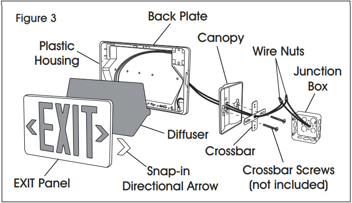
- Attach crossbar to the junction box. Set the crossbar so that the longer blade is touching the junction box. (See Figure 3)
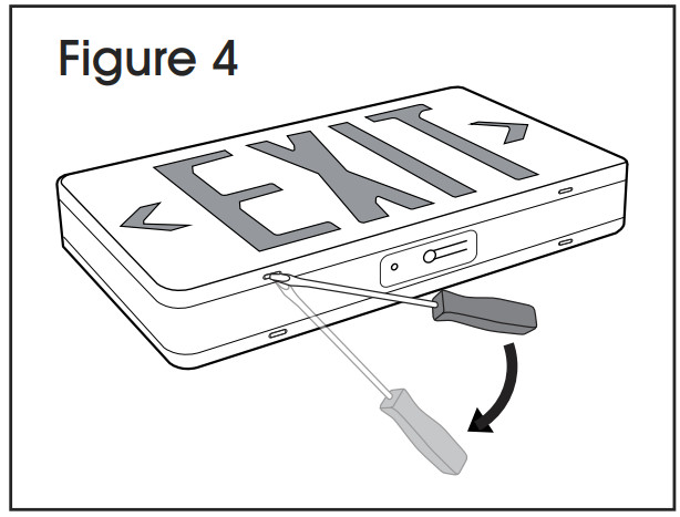
- Open the EXIT housing. (See Figure 4) Feed the transformer input leads through a side-hole, being sure to secure the wire into wire guides molded at the edges of the sign. (See Figure 3)
- Attach sign to the canopy by inserting canopy into a sign at an angle, then twisting to secure. (See Figure 3)
- Make the proper supply lead connections. If using 120VAC, connect the black and white leads to the building utility. If using 277VAC, connect the orange and white leads to the building utility. Cap off the unused wire. If the unit is self-powered, be sure to snap the battery connector together.
- Feed the excess wire into the junction box and align holes in the canopy with holes in the crossbar. Use screws supplied to tighten the canopy to the crossbar so the canopy is securely fastened and tight against the wall. (See Figure 3)
- Snap-in arrows to EXIT panel as required. Then snap EXIT panel to housing: top first then the bottom.
CEILING MOUNTING
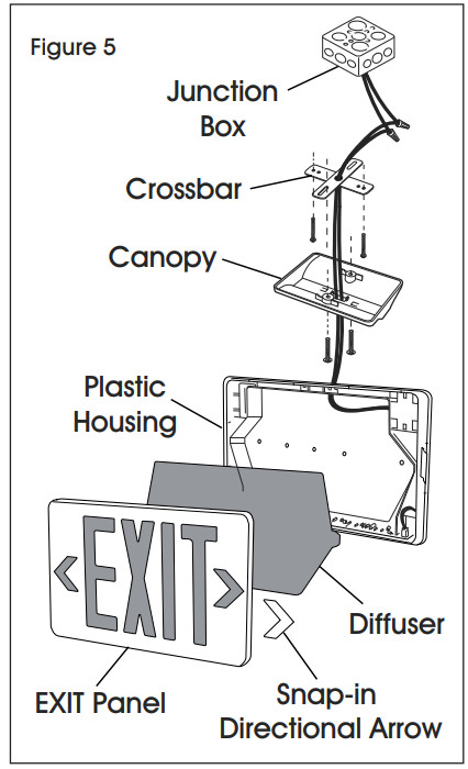
- Attach crossbar to the junction box. Set the crossbar so that the longer blade is touching the junction box. (See Figure 5)
- Open the EXIT housing. (See Figure 4) Feed the transformer input leads through the top hole, being sure to secure the wire into wire guides molded at the edges of the sign.
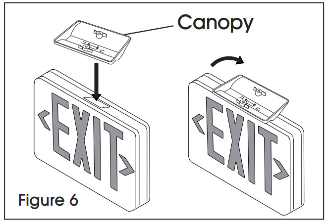
- Attach sign to the canopy by inserting canopy into a sign at an angle. Twist to secure. (See Figure 6)
- Make the proper supply lead connections. If using 120VAC, connect the black and white leads to the building utility. If using 277VAC, connect the orange and white leads to the building utility. Cap off the unused wire. If the unit is self-powered, be sure to snap the battery connector together.
- Feed the excess wire into the junction box and align holes in the canopy to the crossbar so that canopy is securely fastened and tight against the ceiling.
- Snap-in arrows to EXIT panel as required. Then snap EXIT panel to housing: top first, then the bottom.
BATTERY
![]() CAUTION! The Battery Connector is shipped disconnected. Snap connector into the socket at installation. (See Figure 7)
CAUTION! The Battery Connector is shipped disconnected. Snap connector into the socket at installation. (See Figure 7)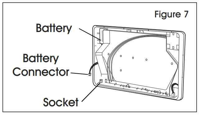 Use Manual Battery Test Switch on the base of the unit to test. Red LED indicates normal operation. (See Figure 8)
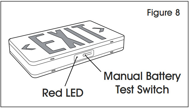
![]()
1-800-295-5510uline.com0621 IH-1663
[xyz-ips snippet=”download-snippet”]