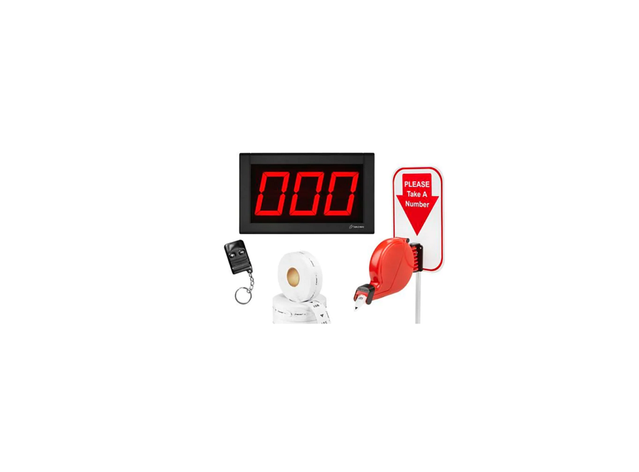
ULINE H-1713, H-2770 Take-A-Number Wireless System Installation Guide

TOOLS NEEDED

Large Flathead Screwdriver

Mini Flathead Screwdriver

Phillips Screwdriver
PARTS
COUNT PIECES BEFORE ASSEMBLING
CONTENTS OF MEDIUM BOX (Dispenser)

CONTENTS OF A SMALL BOX (Wireless Push Button Set)

Display Wall Mount Bracket x 1
 Wireless Receiver x 1

Wireless Push Button x 2NOTE: Spare wireless push button in plastic bag is not programmed. See page 6 for programming instructions.
 “Please Take A Number” Sign x 1
 Label Sheet x 1

CONTENTS OF LARGE BOX (Display)

 Display x 1 (H-1713) Display x 1 (H-2770)
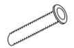
 Wall Anchor x 2 Large Phillips Screw x 2
CONTENTS OF LARGE RECLOSABLE BAG (Stand and Power Supply)

 Power Extension Cable (10 ft.) AC Power Supply x 1
 Country Outlet Adapter x 4

Allen Wrench x 1 (used to disconnect bottom base from stand post)Mounting Stand x 1
OPERATION AND USE OF DISPENSER
OPERATION
- Customer takes a number from the dispenser and waits until the number appears on the display.
- Press (+) on the wireless push button once to display the next time
- Press and hold (+) on the wireless push button to advance the numbers by tens
- Use (–) on the wireless push button to go back one number at a TIME
NUMBER DISPENSER
Number dispenser can be mounted to either the wall or stand.
WALL MOUNTING
- Mark mounting holes on wall using dispenser mounting bracket as a (See Figure 1)
- Drill holes using 3⁄16″ to 5⁄16″ drill bit.
- Use wall anchors if attaching to surfaces other than solidFigure 1
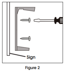
- Position sign and dispenser mounting bracket (longer holder at the top) over holes in wall and fasten with two slotted screws.(See Figure 2)

- Snap dispenser into mounting(See Figure 3)

STAND MOUNTING
- Position mounting stand in the desired location on countertop.
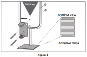
![]() NOTE: for clean, smooth surfaces, remove backing from adhesive strips on the base of the mounting stand and secure to surface.
NOTE: for clean, smooth surfaces, remove backing from adhesive strips on the base of the mounting stand and secure to surface.
![]() NOTE: for permanent mounting, use the base of mounting stand as a template, mark and drill four holes and secure base of stand to surface with four screws (not included).
NOTE: for permanent mounting, use the base of mounting stand as a template, mark and drill four holes and secure base of stand to surface with four screws (not included).
- Align holes in sign and mounting bracket (longer holder on top) with holes in Push two large slotted bolts through bracket and sign and secure with nuts. (See Figure 4)
- Snap dispenser into mounting (See Figure 3)
LOADING DISPENSER
- Pull down locking bar to open dispenser.
- Drop in number roll (not included) so the numbers roll out from the bottom. (See Figure 5)
- Pull end of roll through end of dispenser. Close dispenser and snap locking bar back into place.

DISPLAY – MOUNTING AND INSTALLATION
ELECTRONIC DISPLAY
MOUNTING BRACKET TO WALL
- Determine where to place the display so it is easily seen by costumers.
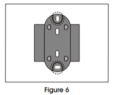
- Mark mounting holes on wall using the display wall mount bracket as a (See Figure 6)
- Drill holes using 5⁄16″ drill bit.
- Use wall anchors (included) if attaching to surfaces other than solid wood
- Position display wall mount bracket over drilled holes and fasten with two large Phillips (See Figure 7)

CONNECTING AC POWER SUPPLY
- Plug the AC power supply into either of the two power receptacles located on the back of the display. (See Figure 8)
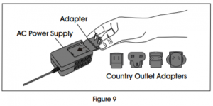
- Choose the appropriate country outlet adapter and slide it into the AC power (See Figure 9)
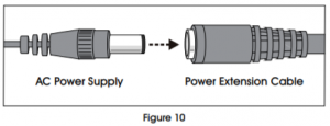
- Attach 10 power extension cable if necessary. (See Figure 10)
- Plug the AC power supply into the nearest outlet.

CONNECTING WIRELESS RECEIVER
- Place the pin connector of the wireless receiver on the pins located on the back of (See Figure 11)
- Remove backing from adhesive strips on the wireless receiver and mount it on the back of the display.

SETUP
SETTING SOUND TONE AND VOLUME
Use a mini flathead screwdriver to change the tone and volume switches on back of the display. (See Figure 12) Set the sound tone with switches 1-2:
- No sound: 1-OFF, 2-OFF
- Single tone: 1-OFF, 2-ON
- Double tone: 1-ON, 2-OFF
- Triple tone: 1-ON, 2-ON
Set the volume with switches 3-4:
- Low volume: 3-OFF, 4-OFF
- Medium volume: 3-ON, 4-OFF (recommended in most cases)
- High volume: 3-OFF, 4-ON
- Highest volume: 3-ON, 4-ON

DISPLAY START-UP
The display shows a number of messages on start-up once it is plugged in. (See Figure 13) Display shows:
- Program version: “P-“, then number
- TOM-Net address: ‘ad”, then 51 or 21
- Last number displayed when power was disconnected: Number, (“00” if first-time start-up.)
- Error message if display is set as a duplicate master: “Ed”

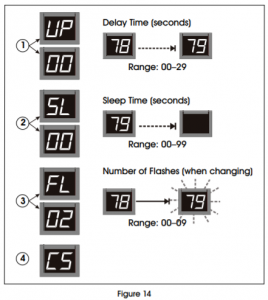
OPTIONAL DISPLAY SETUP (See Figure 14)
To enter setup options, make sure display is unplugged. Hold down (+) on the wireless push button and plug the display back in. Release (+) when display shows “UP.”
- Set display update delay:
- Display shows “UP” followed by the current delay time in seconds, (ex. “00”). Press (+) on the wireless push button to increase the delay one second at a
- After three seconds without pushing the button, the set display sleep time “SL”
- Set display sleep time:
- Display shows “SL” followed by the current setting in (The display shuts off after a set period of time with no button pushes.) Press (+) on the wireless push button to increase the delay before the display goes into sleep mode one minute at a time.
- After three seconds without pushing the button, the set display flashes and “FL” appears.
- Set display flashes when number changes:
- Display shows “FL” followed by the current setting showing number of flashes. Press (+) on the wireless push button to increase the number of times the display will flash when the number changes one flash at a time.
- After three seconds without pushing the button, the display shows “CS” and saves new settings to memory.
INSTALLING ADDITIONAL DISPLAYS
- See instructions included with H-2769 or H-4665.
![]() NOTE: The wireless push button codes must be copied to the wireless receiver. The maximum number of wireless push buttons per wireless receiver is 15.
NOTE: The wireless push button codes must be copied to the wireless receiver. The maximum number of wireless push buttons per wireless receiver is 15.
![]() NOTE: Individual wireless push button codes cannot be changed or deleted. All codes must be deleted to start over with new codes.
NOTE: Individual wireless push button codes cannot be changed or deleted. All codes must be deleted to start over with new codes.
- Press #1 on the wireless receiver and hold for three The green LED light on the back of the wireless receiver will start blinking. (See Figure 15)
- Release #1 on the wireless receiver. Then press the (+) button on the wireless push button. The green LED light will stop blinking. (See Figure 16)
- Press #2 on the wireless receiver and hold for three The red LED light on the back of the wireless receiver will start blinking. (See Figure 15)
- Release #2 on the wireless receiver. Then press the (–) button on the wireless push button. The red LED light will stop (See Figure 16)
- Press #1 on the wireless receiver for three seconds. Release and press #1 again for three seconds. The code has been (See Figure 15)
- Press #2 on the wireless receiver for three seconds. Release and press #2 again for three seconds. The code has been (See Figure 15)


Read More About This Manual & Download PDF:
[xyz-ips snippet=”download-snippet”]