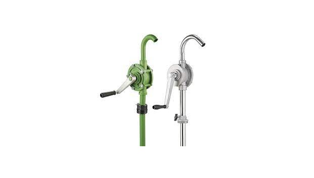
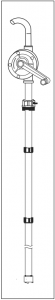
H-4377 ROTARY DRUM PUMP
1-800-295-5510uline.com
TOOLS NEEDED
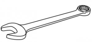
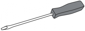
1/2″ (13 mm) Wrench Flathead Screwdriver
SPECIFICATIONS
Pump Type Rotary – VaneFlow 8 GPM (12 oz / Stroke)Maximum Fluid Temperature 130°F / 54°CBung Adapter 2″ MaleSuction Tube Length 40″ MaximumInlet 1¼” O.D.Outlet 1″ O.D. Curved SpoutWetted Parts PP, PVDF, PTFE, 304SS & EPDMMaximum Viscosity 1,000 cps
OPERATING INSTRUCTIONS
 IMPORTANT! This pump is made out of polypropylene, PVDF, PTFE, 304 stainless steel and EPDM. Use chemicals compatible with these materials and follow OSHA guidelines when using this pump, including proper grounding and protective gear as required. Unit not UL or FM approved.
- Rotate handle clockwise several times to prime. If unit does not prime after a few turns, pouring some fluid into pump inlet may help free pump.
- For siphoning, position handle straight down.
- To stop siphoning, rotate handle 1/4 turn (leave handle in horizontal position).
- After using pump, position handle straight down. Liquid will drain back into the container.
- If pump is removed from drum, rinse it thoroughly in a liquid that is compatible with both the pump and the fluid being pumped.
- Regularly check pump and suction tubes for leaks. Leaks in the suction line or in pump housing will cause inefficient pumping and loss of prime.
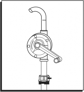
ASSEMBLY AND INSTALLATION
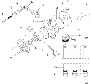
# DESCRIPTION QTY.1 Pump Body 12 Rear Cover 13 Front Cover 14 Rotor 15 Vane 26 Spring 17 Spring Rod 18 Lip Seal 19 Discharge Spout 110 Cap Screw 411 Cap Screw 612 O-Ring 213 Hex Bridge 214 Crank Arm 115 Set Screw 116 Handle 117 Handle Shaft 118 Hex Nut 119 Bung Adapter 120 Suction Tube 321 Tube Connector 222 Suction Filter 1
1. Check to see if all parts are included.2. Screw discharge spout (9) into pump body (1) outlet using PTFE sealant tape provided.
CAUTION! Do not use pipe sealant.
3. In order to avoid leakage, use PTFE sealant tape (included) to seal three suction tubes (20) with two tube connectors (21).4. Attach bung adapter (19) onto the top of the assembled suction tube. Screw assembled suction tube into pump body (1).5. Insert handle shaft (17) through handle (16). Turn hex nut (18) onto handle shaft until handle rotates freely.6. Screw assembled handle to crank arm (14). Keep handle shaft from turning. Tighten hex nut (18) against crank arm. Then insert crank arm assembly onto rotor (4), taking care to align set screw (15) to indent in rotor shaft.7. Insert assembled pump into drum and hand tighten the fixed screw onto bung adapter (19). Be sure to set pump and assembled suction tube so that the suction tube is at the desired depth in the drum and is not blocked.
1-800-295-5510uline.com
0721 IH-4377
[xyz-ips snippet=”download-snippet”]