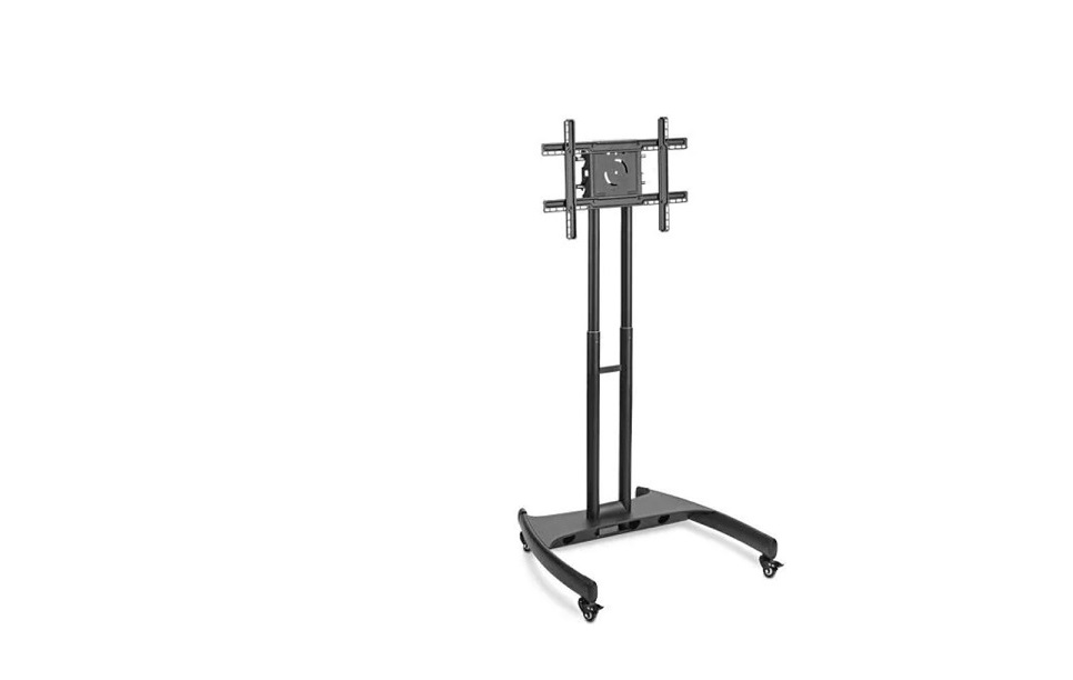
ULINE H-5487 Flat Screen Cart Installation Guide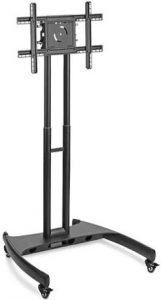
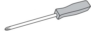
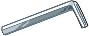
TOOLS NEEDED
- Phillips Screwdriver

- Allen Wrench
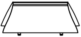
- Base x 1
- Caster x 4
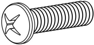
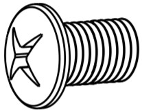
- Mounting Bolt A x 4 (M8 x 25mm)
- Bolt Cover x 1
- Mounting Plate x 1
- Cable Guard x 4
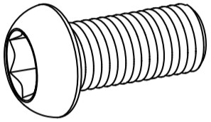
- Mounting Bolt B x 4 (M6 x 25mm)
- Mounting Bolt C x 4 (M5 x 25mm)
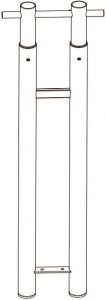
- Upright Assembly x 1
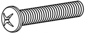
- Base Bolt x 4 (M8 x 20mm)
- Crossbar x 1
- Spacer x 4
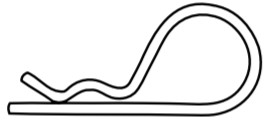
- Cotter Pin x 1
- Bar Bolt x 8 (M6 x 10mm)
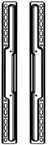
- Short Vertical Mounting Bar x 2
- Long Horizontal Mounting Bar x 2
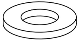
- Washer x 4
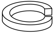
- Lock Washer x 4


SAFETY
![]() WARNING! Severe personal injury and property damage can result from improper installation.Read instructions carefully before beginning.
WARNING! Severe personal injury and property damage can result from improper installation.Read instructions carefully before beginning.
- Do not install or assemble if the product is damaged or hardware is missing.
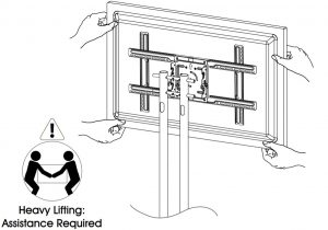
- This product fits most 32-60″ flat panel displays; maximum weight for the display is 100 lbs. (45.5 kg).
- Do not use this product for anything other than what it was originally designed.
ASSEMBLY
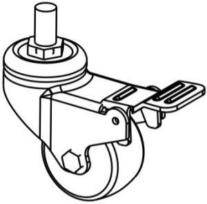
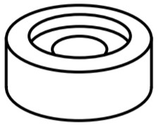
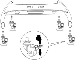
- Lock casters. Place lock washer over caster stem and screw into base. (See Figure 1)
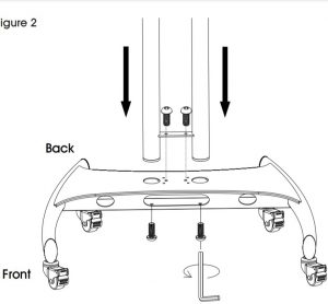
- Insert upright assembly into base with cable management holes facing back of unit. Fasten in place with four base bolts. (See Figure 2)
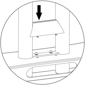
- Snap bolt cover into place. (See Figure 3)
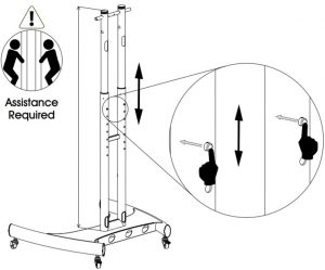
- . Adjust uprights to desired height using plunger buttons. (See Figure 4) NOTE: Never adjust height with the cables connected or flat screen mounted.
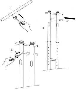
- Unscrew pre-installed bolts from crossbar. Slide crossbar into position and screw bolts back into place. (See Figure 5)
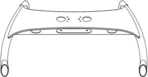
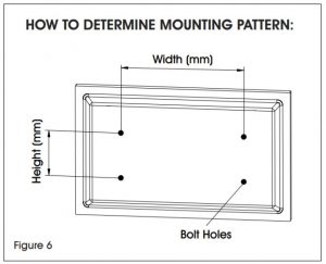
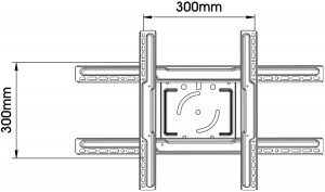
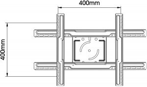
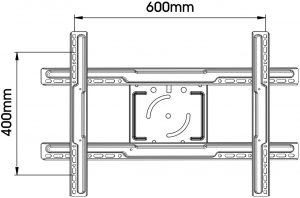
- Check your flat screen to determine the mounting pattern and mounting bolt size needed. Several common mounting patterns are shown here. (See Figures 6-7) NOTE: Test bolt size in flat screen to determine correct size.Mounting Bolt A – Used on flat screens with larger 8mm bolt holes.Mounting Bolt B – Used on flat screens with medium 6mm bolt holes.Mounting Bolt C – Used on flat screens with smaller 5mm bolt holes. NOTE: If flat screen is already mounted on a pedestal, remove pedestal prior to mounting.
- Attach mount assembly to flat screen. NOTE: Spacers should be used between mounting bars and flat screen to avoid damage. (See Figure 8)FOR 200mm x 200mm MOUNTING PATTERNS:If using a 200mm x 200mm mounting pattern, attach mounting plate directly to flat screen using mounting bolts, washers and spacers. (See Figure 9)FOR ALL OTHER MOUNTING PATTERNS:For all larger mounting patterns, attach long horizontal mounting bars to mounting plate using four bar bolts. (See Figure 10) NOTE: To correctly position horizontal mounting bars, make sure oval mounting holes are on the bottom and the lips face the mounting plate. NOTE: To correctly position vertical mounting bars make sure oval mounting holes are centered at the width of your mounting pattern and the lips face the mounting plate. NOTE: Before continuing to step 8, make surecasters are in the locked position. (See Figure 13)
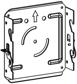
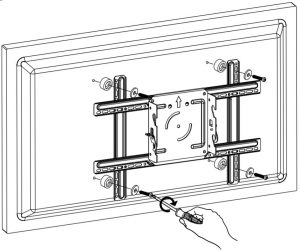
- Lift lock hooks on mounting plate. (See Figure 14)
- Lift flat screen and hook mounting plate onto crossbars. (See Figure 15)
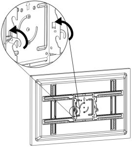
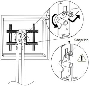
- Secure flat screen by engaging lock hook and fastening with cotter pin. (See Figure 16)
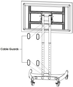
- Snap cable guards into place. (See Figure 17)
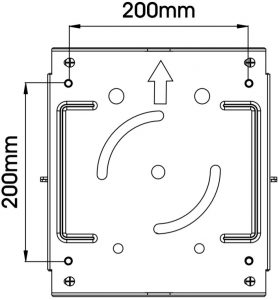
 FOR 200mm x 200mm MOUNTING PATTERNS:If using a 200mm x 200mm mounting pattern, attach mounting plate directly to flat screen using mounting bolts, washers and spacers. (See Figure 9)
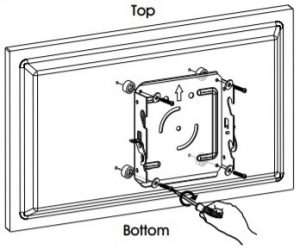 FOR ALL OTHER MOUNTING PATTERNS:For all larger mounting patterns, attach long horizontal mounting bars to mounting plate using four bar bolts. (See Figure 10)
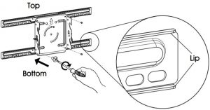
 1-800-295-5510uline.com
[xyz-ips snippet=”download-snippet”]