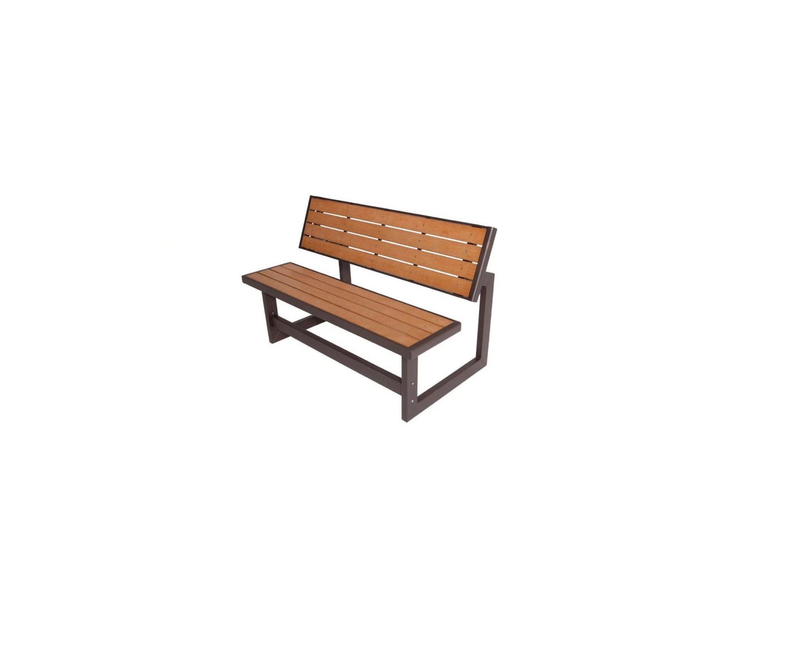
ULINE H-5947 Convertible Bench Installation Guide

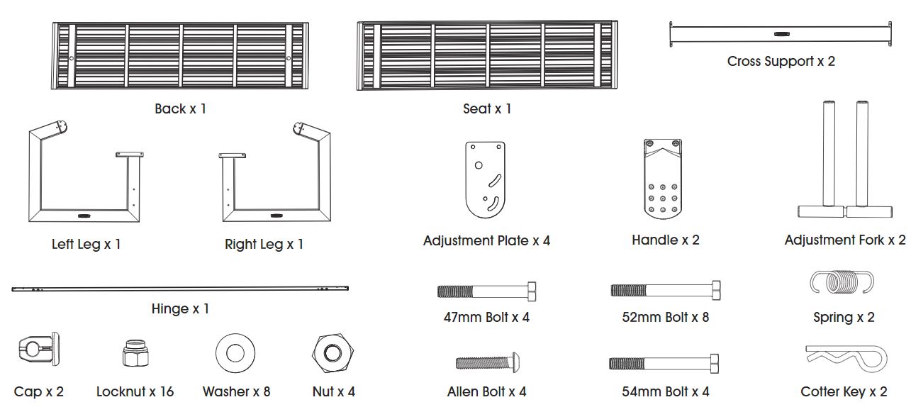
PARTS
SAFETY
- Level Ground: Assemble the table on level ground.
- Recruit Friends and Family: Assembly takes two capable adults about one hour to complete.
 CAUTION! Failure to follow these warnings may result in serious injury or property damage and will void warranty.
 - To ensure safety, do not attempt to assemble this product without following the instructions carefully.
- Assemble on a level surface.
-
Be aware that plastic pieces can be damaged by overtightening the screws.
-
All who participate in assembly must wear safety glasses throughout the process.
-
Do not use or store hot objects near the product.
-
Proper and complete assembly are essential to reduce the risk of accident or injury.NOTE: Most injuries are caused by misuse and/or not following instructions.
ASSEMBLY
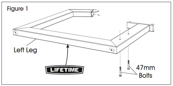
1. Insert two 47mm bolts through the holes in the left leg. (See Figure 1)![]() NOTE: Orient the Lifetime logo as shown.
NOTE: Orient the Lifetime logo as shown.
2. Set the two holes in the cross support over the two 47mm bolts and secure with locknuts. Do not overtighten. (See Figure 2)![]() NOTE: Orient the Lifetime logo as shown.
NOTE: Orient the Lifetime logo as shown.

3. Secure the cross support to the right leg with 47mm bolts and locknuts. Do not overtighten. (See Figure 3)

4. Set the seat down onto the legs as shown and align the holes. (See Figure 4)
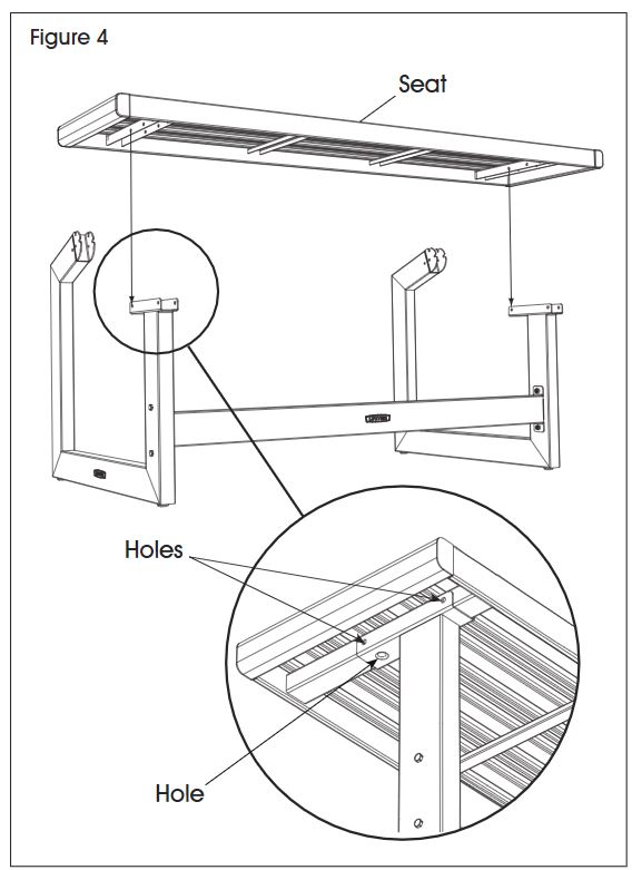
5. Secure the seat to the leg with 52mm bolts and locknuts. Do not overtighten. (See Figure 5)![]() NOTE: Repeat this step for the other leg.
NOTE: Repeat this step for the other leg.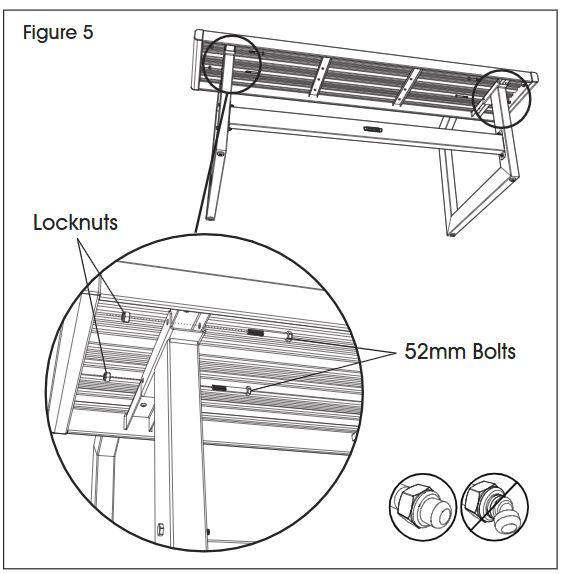
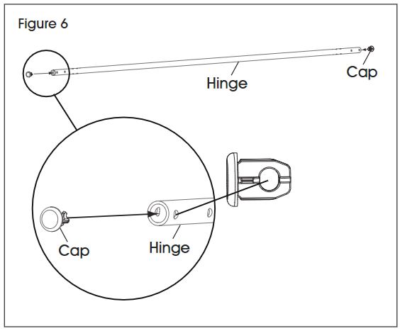
6. Insert a cap into both ends of the hinge. (See Figure 6)
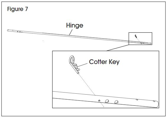
7. Insert a cotter key into the small hole in the hinge. (See Figure 7)
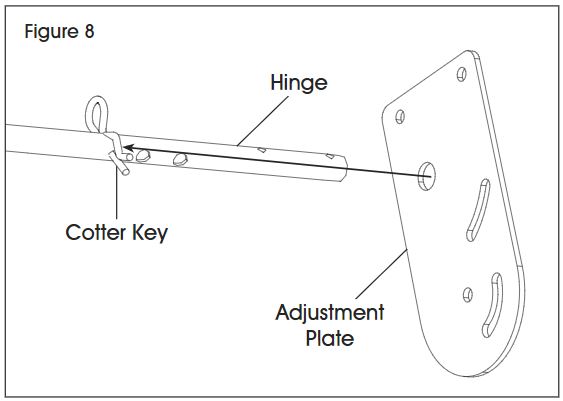
8. Slide an adjustment plate over the end of the hinge and up to the cotter key. (See Figure 8)
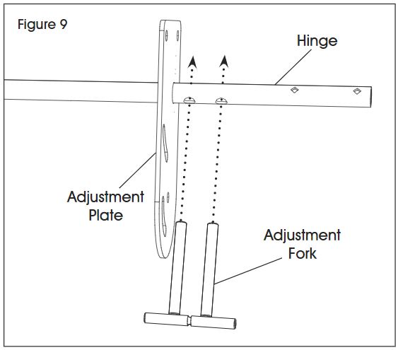
9. Insert an adjustment fork into the two larger holes in the hinge. (See Figure 9)
10. Slide another adjustment plate over the end of the hinge and adjustment fork. (See Figures 10-11)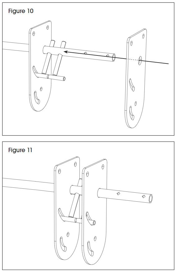
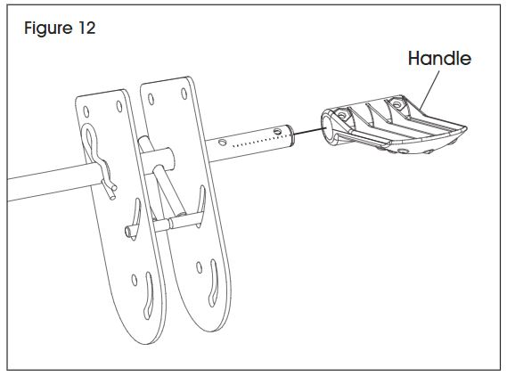
11. Slide a handle onto the hinge. (See Figure 12)
12. Secure with two Allen bolts and nuts with the Allen wrench. (See Figure 13)
![]() NOTE: The nuts fit into the nut-shaped indentations in the handle.
NOTE: The nuts fit into the nut-shaped indentations in the handle.

3. Repeat steps 7-12 for the other side of the hinge.
14. Set the hinge assembly onto the back of the legs and align the holes. (See Figure 14)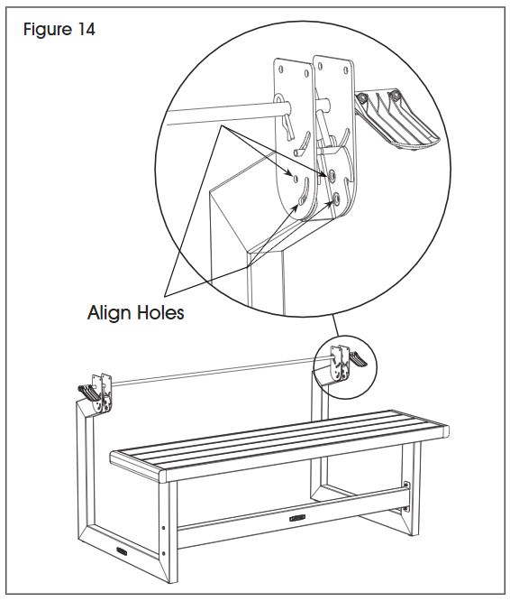
15. Attach hinge assembly to the leg using two 54mm bolts, four washers and two locknuts. (See Figure 15)
![]() NOTE: Repeat for the other side.
NOTE: Repeat for the other side.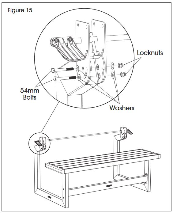
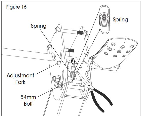
16. Using pliers, attach a spring to the adjustment fork and 54mm bolt. (See Figure 16)![]() NOTE: Repeat for the other side.
NOTE: Repeat for the other side.
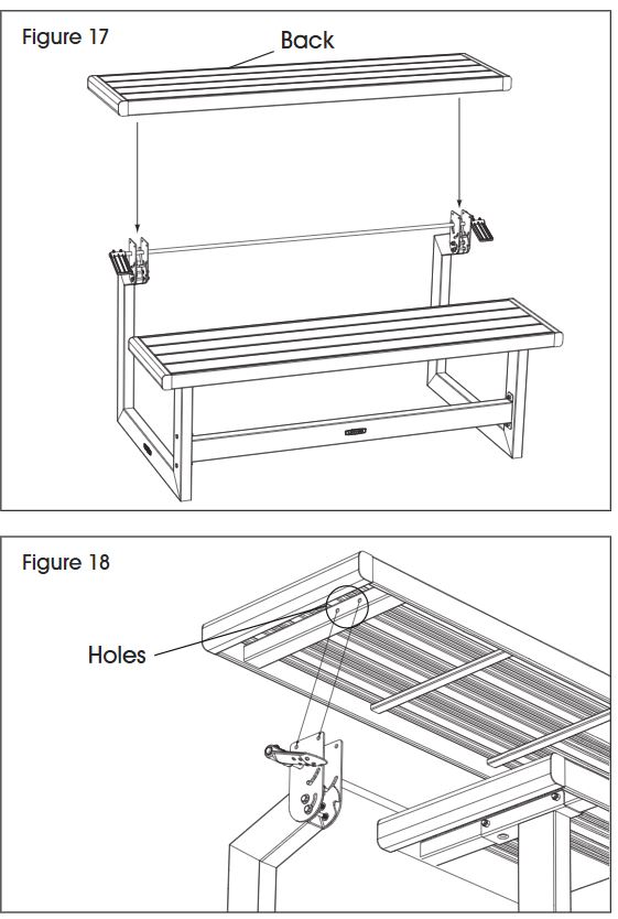
17. Secure the back to the legs with two 52mm bolts and locknuts. (See Figures 17-19)![]() NOTE: Align holes per Figure 18.
NOTE: Align holes per Figure 18.
18. Loosen the locknuts just enough to allow you to rotate the handle. Tighten only by hand at this point. (See Figure 19)
![]() NOTE: Repeat for the other side.
NOTE: Repeat for the other side.

19. Adjust the back until it is level. Tighten the hardware from the previous step with 8 x 10mm wrench. (See Figure 20)
![]() NOTE: Repeat for other side.
NOTE: Repeat for other side.
OPERATION
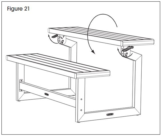
BACK ADJUSTMENTTo switch from bench to table, simply pull up on the handles and rotate the back downward and vice versa. (See Figure 21)
MAINTENANCE
CLEANING AND CAREBy following the instructions, your new product should provide you with years of service and enjoyment.The panels are stain- and solvent-resistant. Most stains can be removed using a mild soap and a soft-bristled brush.
![]() NOTE: Abrasive cleaning materials may scratch the plastic and are not recommended. Repair scratches or rust spots on the metal by sanding the affected area lightly, using a rust preventative spray primer, and spraying with a high-gloss spray enamel paint.
NOTE: Abrasive cleaning materials may scratch the plastic and are not recommended. Repair scratches or rust spots on the metal by sanding the affected area lightly, using a rust preventative spray primer, and spraying with a high-gloss spray enamel paint.
![]() CAUTION! Avoid placing a direct heat source on or near surfaces unless using a heat barrier.
CAUTION! Avoid placing a direct heat source on or near surfaces unless using a heat barrier.
![]()
1-800-295-5510uline.com
[xyz-ips snippet=”download-snippet”]