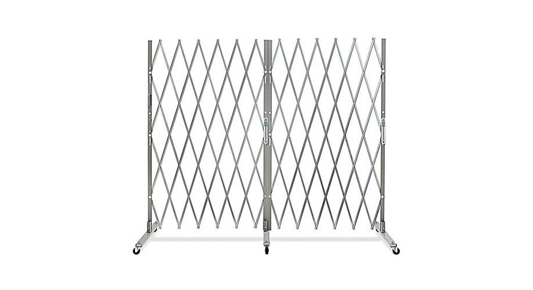
 H-6375, H-6376H-6377, H-6378HEAVY-DUTY FOLDINGSECURITY GATE

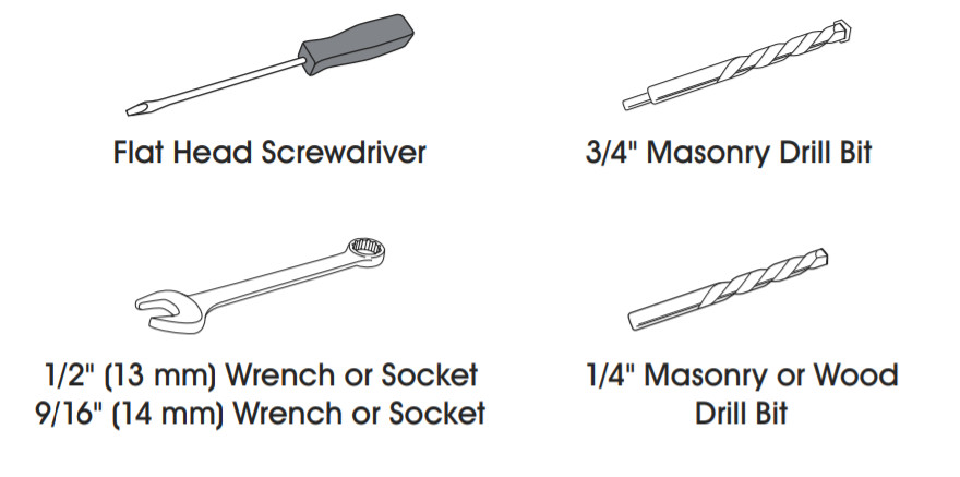
TOOLS NEEDED
PARTS NEEDED
5/16 x 2″ Long Lag BoltMasonry Door Frame or Wall Installations (Wall Installations may require lead anchors)
PARTS

INSTALLATION
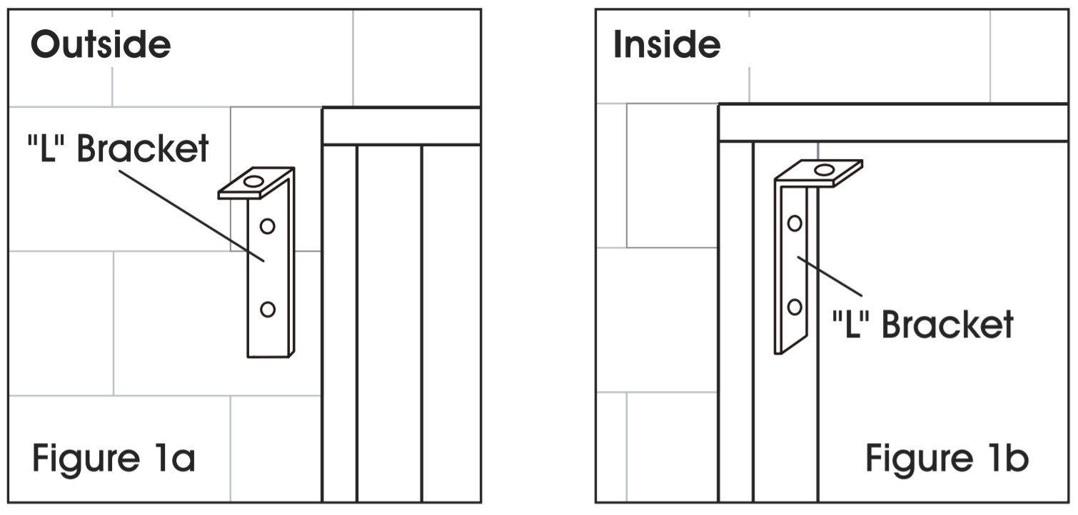
- Before installing, decide on gate placement. “L” brackets that form the top hinge allow gate placement in the recess of the door frame. Installation can either be made outside or inside of the wall next to the door or opening frame. (See Figures 1a and 1b)
 NOTE: Either side of the gate can be toward the outside of the building. A label on the operating side (the side with the center pins) indicates the RHT (right) or LFT (left) of a person facing the operating side.
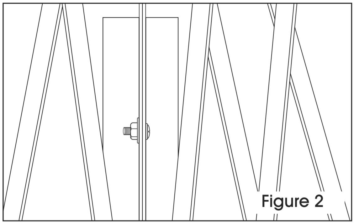
 - Bolt inner and outer panels together at the top, middle and bottom by using carriage bolts, standard washers, and small nuts. Repeat for remaining gate panels. (See Figure 2)CAUTION! Keep hands and fingers out of moving diamonds of the web when handling the gate to avoid pinching.
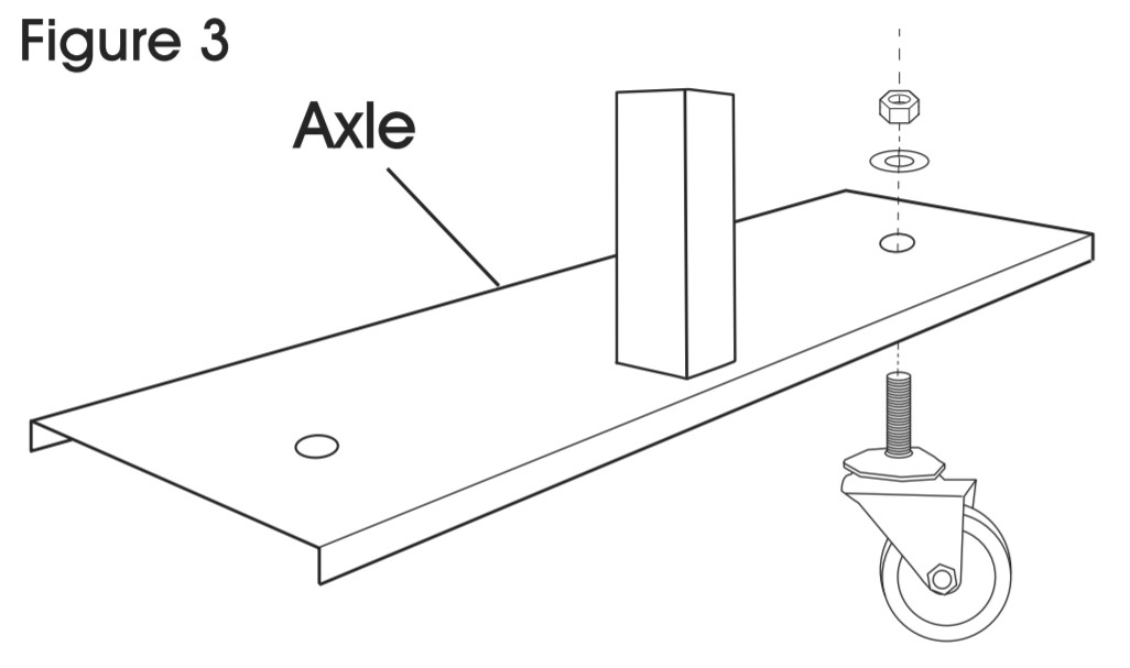
- Attach casters to axles. Put caster through the opening in the axle and tighten with caster washer and large nut. (See Figure 3) Repeat for the remaining three casters.
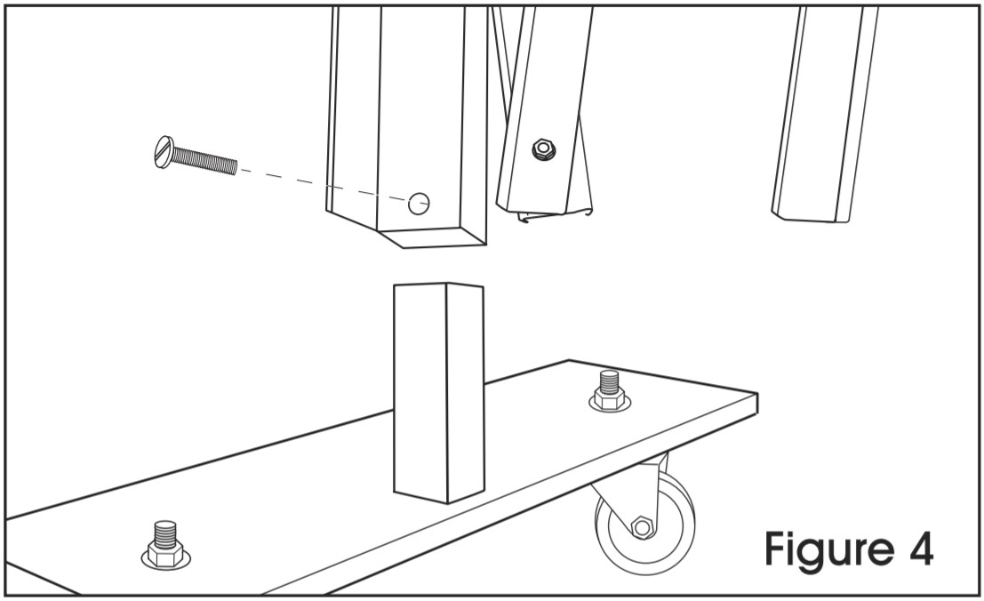
- Insert each gate end onto axle support. Insert the round head bolt and tighten with a screwdriver. (See Figure 4)
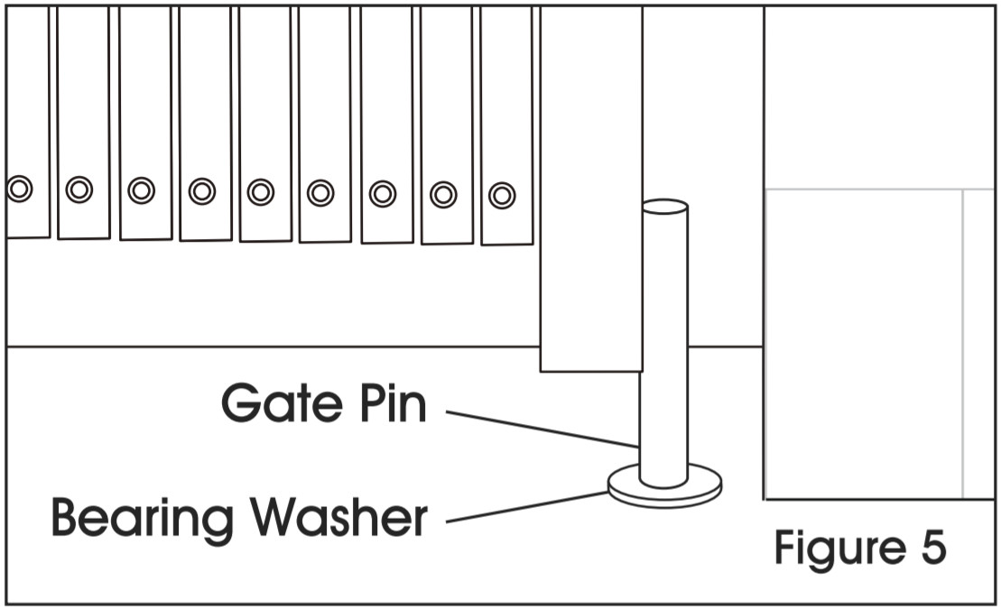
- Have a helper extend the gate and stand it upright where it will be mounted. Drill a 3/4″ diameter x 3″ deep hole, 1/” from the wall into the floor for the gate pin to set into. Place a bearing washer over the floor hole and set the bottom gate pin into the floor mount hole. (See Figure 5) Repeat on another side.CAUTION! Check to confirm gate will swing away from opening when not in use. This will provide a clear opening for normal traffic.
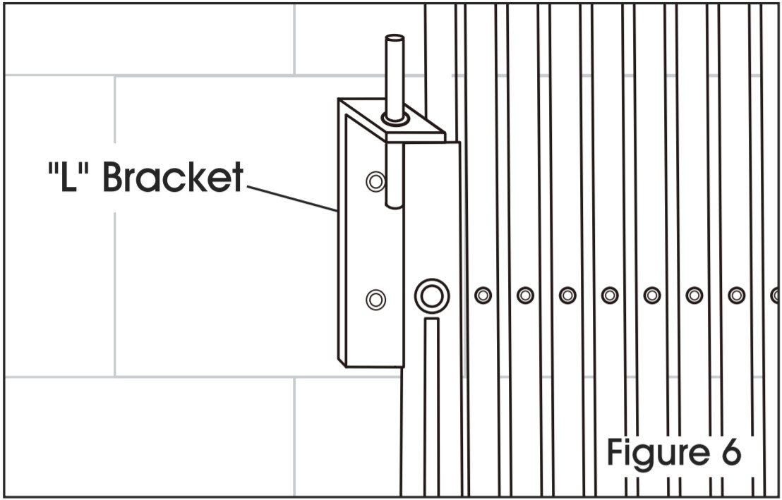
- Extend gate and hang “L” bracket on top of the gate to verify where it will be mounted. To release tension, lift the wheel 1/2 – 3/4″ off the floor. Mark and drill pilot holes into the door frame or wall. It may be easier to drill pilot holes if you remove the gate from its floor mount. Place a bearing washer and bottom gate pin back into the floor mount. Slip “L” bracket over the top of the gate and 5/16 x 2″ lag bolt (not included.) (See Figure 6)• Wood door frames or walls: 5/16 x 2″ lag bolts.• Steel door frames or walls: drill and tap for 5/16 x T lag bolts.• Brick or concrete frames or walls: 5/16 x T lag bolts set Into 3/8° holes with lead anchors.
- Raise center and side pins and use attached notch to keep in place; this prevents damage to the floor surface. (See Figure 7) Extend and retract the gate to its stops to work out the stiffness.CAUTION! Notice that pins at this stage hit the other half of the gate or rest on the floor. Do not cut off pins.
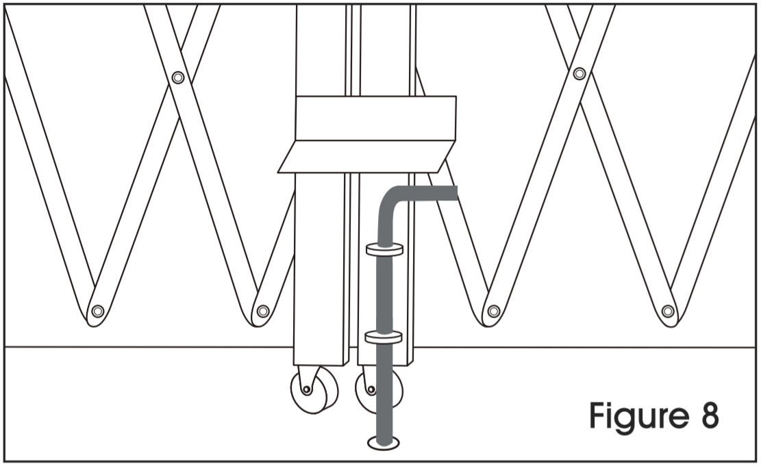
- With pins raised, extend both halves of gates together to the center of the opening, mark floor for the center pin and drill a 3/4″ diameter x 3″ deep hole. Lower pin. Repeat for side pins. Open gates slowly at first to avoid warping. (See Figure 8)

1-800-295-5510uline.com
[xyz-ips snippet=”download-snippet”]