
 H-6953
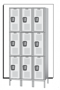
CLEAR-VIEW LOCKER 3 TIER, 3 WIDE1-800-295-5510 | uline.com
TOOL NEEDED
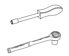 3⁄8″ Nut Driveror3⁄8″ Socket Wrench
H-6953 Clear-View Locker 3 Tier 3 Wide
 CAUTION! Some parts may have sharp edges. Care must be taken when handling various pieces to avoid injury. For your safety, wear work gloves when assembling.
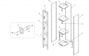
PRIMARY ASSEMBLY
| # | DESCRIPTION | QTY. |
| 1 | Back Panel | 3 |
| 2 | Side Panel | 4 |
| 3 | Top/Bottom/Middle Panels | 12 |
| 4 | Double Ceiling Hook | 9 |
| 5 | Door Frame Assembly | 3 |
| 6 | Door | 9 |
| 7 | Recessed Handle | 9 |
| 8 | Rear Leg | 2 |
| 9 | Number Plate | 9 |
| 10 | Bolt | 188 |
| 11 | Cover Plate | 9 |
| 12 | High-Dome Cap Nut | 18 |
| Push Pin (Not Shown) | 18 | |
| Hex Nut (Not Shown) | 170 |
ASSEMBLY
ASSEMBLING MAIN PANELS![]() NOTE: Do not tighten bolts until unit is completely assembled.
NOTE: Do not tighten bolts until unit is completely assembled.
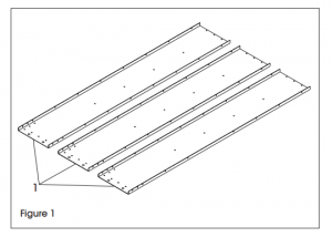
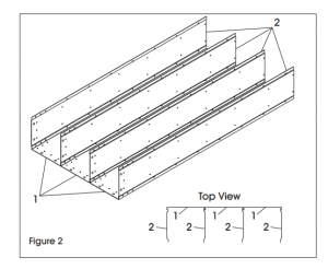
- Place back panels (1) on a protected flat surface so that the flanges face upward. (See Figure 1).
- Bolt side panels (2) to back panels (1), making sure side panels fit inside the flanges of the back panels. The side panels should not go between two back panel flanges. (See Figure 2) The ends of the back and side panels with the two large holes are at the bottom of the locker.NOTE: Do not put nuts and bolts in the bottom three holes in two outside corners. Those will be used later to attach legs.NOTE: Bolts will be shared between panels that are next to each other.
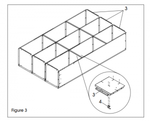
- Bolt top (3), bottom (3) and middle panels (3) to back panels (1) and side panels (2). Only bolt through middle hole when attaching to back panels. (See Figure 3)NOTE: Bolts will be shared between shelves and panels that are next to each other.
- Install one double ceiling hook (4) in each locker opening. (See Figure 3)
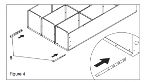
- Insert rear legs (8) into the corner between the bottom and the side. Bolt the leg to the side and back using six bolts and nuts per leg. (See Figure 4)
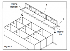
- Place door and frame assemblies (5 and 6) over the locker body. Make certain that body sides are inside door frames. Attach top to frame header and the bottom to frame sill. Finish by attaching side panels to door frame. (See Figure 5)
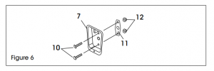
- Attach cover plate (11) to recessed handle (7) using two bolts (10) and high-dome cap nuts (12). (See Figure 6)
- Attach number plates (9) using push pins. (See Figure 7)
- Check and tighten all bolts.
- Stand unit upright and place in desired location.

SECURING UNITS
Anchor units to wall or floor. Unanchored units may fall over if not secured. (Units standing back to back should be bolted together.
CAUTION: Care must be taken to assure that lockers are set plumb and true before anchoring.
![]() 1-800-295-5510uline.com
1-800-295-5510uline.com
References
[xyz-ips snippet=”download-snippet”]