![]()
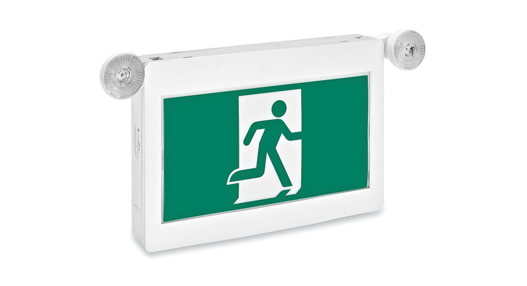
H-7273 RUNNING MAN LED EXIT SIGN1-800-295-5510uline.com
SAFETY
![]() CAUTION! For safety and proper operation, read and follow instructions carefully before and during installation.
CAUTION! For safety and proper operation, read and follow instructions carefully before and during installation.![]() WARNING! Risk of electric shock. Never connect to, disconnect from, or service while a sign is connected to electricity.
WARNING! Risk of electric shock. Never connect to, disconnect from, or service while a sign is connected to electricity.![]() WARNING! Failure to follow these instructions and warnings may result in death, serious injury or significant property damage. Read and follow these warnings and instructions carefully before installing or maintaining this equipment. Instructions do not attempt to cover all installation and maintenance situations.
WARNING! Failure to follow these instructions and warnings may result in death, serious injury or significant property damage. Read and follow these warnings and instructions carefully before installing or maintaining this equipment. Instructions do not attempt to cover all installation and maintenance situations.![]() CAUTION! The battery in this sign may not be fully charged. After electricity is connected, let the battery charge for at least 24 hours before operating. To check the battery, press the test button. The LED sign should illuminate.
CAUTION! The battery in this sign may not be fully charged. After electricity is connected, let the battery charge for at least 24 hours before operating. To check the battery, press the test button. The LED sign should illuminate.![]() CAUTION! When replacing the lamp, use only parts specified in the fixture. Using other lamp types may result in transformer damage or unsafe conditions.
CAUTION! When replacing the lamp, use only parts specified in the fixture. Using other lamp types may result in transformer damage or unsafe conditions.
- Do not use outdoors.
- Equipment should be mounted securely in locations and at heights where it will not readily be subjected to tampering by unauthorized personnel.
- Do not mount near gas or electric heaters.
- Before wiring to power supply, turn off electricity at fuse or circuit breaker.
- Cap unused wires with enclosed wire nuts or other approved methods.
- Do not use this equipment for anything other than intended use.
- The use of accessory equipment not recommended by Uline will void the product warranty and may cause an unsafe condition.
- Use caution when servicing batteries. Battery acid can cause burns to the skin and eyes. If acid is spilled on skin or in the eyes, flush acid with fresh water and contact a physician immediately.
- All service on this equipment should be performed by qualified service personnel only.
- Make sure wire terminations are secure and leads are properly tucked inappropriate wire channels.
INSTALLATION
WALL MOUNTING
- Remove faceplate and backplate and set aside.
- Connect 20-inch jumper leads to AC input leads in J-Box. Fasten the J-Box bracket to J-Box. Use black wired for 120V. Use orange or red wire for 347V. The white wire is common. In some cases, not all lead wires will be used. Cap off the unused wire.
- Remove necessary knockouts and fasten backplate to J-Box cover.
- Snap housing on to backplate.
- Connect and trim input lead. Slide through the hole in the backplate and connect to supply leads in J-Box.
- Connect battery only after continuous AC power can be provided to the unit.
- Secure faceplate(s) to housing.
CEILING MOUNTING
- Remove the faceplate and set aside.
- Connect 20-inch jumper leads to AC input leads in J-box. Fasten the J-Box bracket to J-Box. Use black wired for 120V. Use orange or red wire for 347V. The white wire is common. In some cases, not all lead wires will be used. Cap off the unused wire.
- Fasten canopy to J-Box bracket.
- Remove canopy hole cover on the top and snap housing to the canopy.
- Connect and trim input lead. Slide through the canopy and connect to supply leads in the J-Box.
- Connect battery only after continuous AC power can be provided to the unit.
- Secure faceplate(s) to housing.
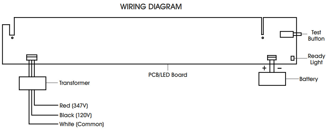
WIRING DIAGRAM
![]()
800-295-5510uline.mx0621 IH-7273
[xyz-ips snippet=”download-snippet”]