![]()
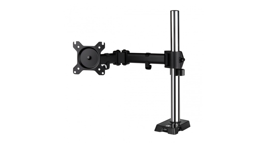
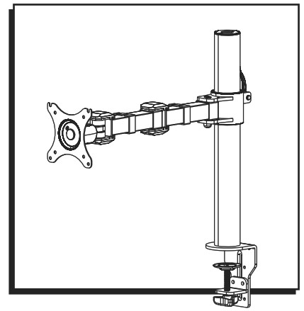
H-7618SINGLE MONITOR MOUNT STANDARD
1-800-295-5510uline.com
TOOLS NEEDED
|
Phillips Screwdriver |
3 x 3 Allen Wrench4 x 4 Allen Wrench (F)5 x 5 Allen Wrench (G)6 x 6 Allen Wrench (all included) |
Two Person Assembly Required |
PARTS
| # | DESCRIPTION | QTY. |
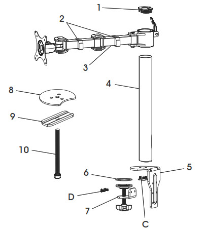
| 1 | Tube Cover | 2 |
| 2 | Cable Clip | 2 |
| 3 | Monitor Arm | 1 |
| 4 | Tube | 1 |
| 5 | Clamp Mounting Bracket | 1 |
| 6 | Anti-Slip Foam | 1 |
| 7 | Clamp | 1 |
| 8 | Grommet Mounting Plate | 1 |
| 9 | Bottom Support | 1 |
| 10 | Grommet Bolt | 1 |
| A | M4 x 12 mm Bolt (Not Shown) | 4 |
| B | M5 x 12 mm Bolt (Not Shown) | 4 |
| C | M6 x 20 mm Bolt | 3 |
| D | M6 x 10 mm Bolt | 2 |
| E | Flat Washer (Not Shown) | 8 |
SETUP
![]() NOTE: Make sure the monitor has a VESA hole pattern of 75 x 75 mm or 100 x 100 mm. (See Figure 1)
NOTE: Make sure the monitor has a VESA hole pattern of 75 x 75 mm or 100 x 100 mm. (See Figure 1)![]() NOTE: If the monitor is attached to a fixed base, remove monitor from base.
NOTE: If the monitor is attached to a fixed base, remove monitor from base.![]() CAUTION! Be careful not to scratch the monitor screen during installation.
CAUTION! Be careful not to scratch the monitor screen during installation.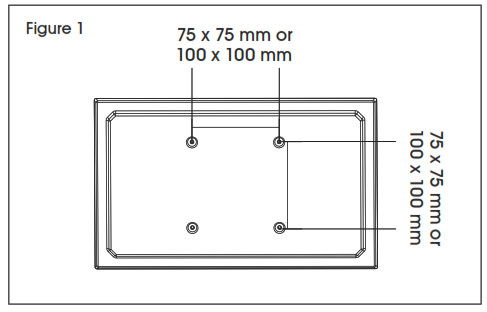
ASSEMBLY
CLAMP MOUNTING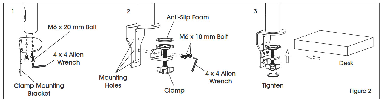
NOTE: Clamp mount is compatible with desk thickness of 3/4 3/”.
- Attach clamp mounting bracket (5) to bottom of tube (4) using M6 x 20 mm bolts (C) and 4 x 4 Allen wrench (F). (See Figure 2)NOTE: Opening near bottom of tube is for cable management. Make sure opening is aligned with the back of clamp mounting bracket.
- Apply anti-slip foam (6) to ring on clamp (7). Select the appropriate mounting holes based on the thickness of the desk. Attach clamp (7) to the clamp mounting bracket (5) using M6 x 10 mm bolts (D) and 4 x 4 Allen wrench (F).
- Place clamp mounting bracket and clamp over desk and fully tighten knob.
GROMMET MOUNTING
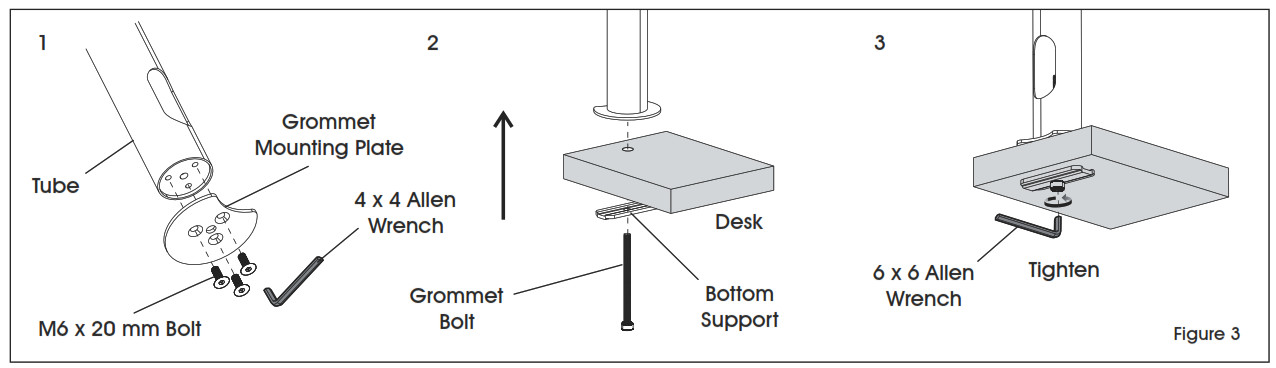
- Attach grommet mounting plate (8) to bottom of tube (4) using M6 x 20 mm bolts (C) and 4 x 4 Allen wrench (F). (See Figure 3)NOTE: Opening near bottom of tube is for cable management. Make sure opening is aligned with indent on grommet mounting plate.
- Thread grommet bolt (10) through bottom support (9). Insert bolt into hole of desk and into center hole in grommet mounting plate (8).
- Fully tighten grommet bolt (10) using 6 x 6 Allen wrench.
ATTACHING MONITOR ARM
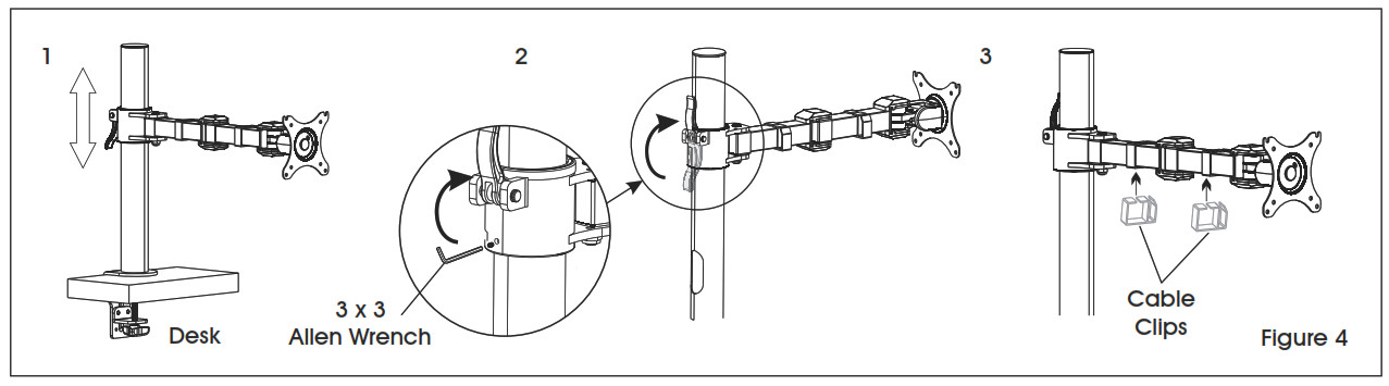
- Place monitor arm (3) over tube (4) and choose desired height of monitor. (See Figure 4)
- Flip lever on monitor arm to lock in place. Using a 3 x 3 Allen wrench, tighten the bolt directly underneath the lever to secure monitor arm. CAUTION! Make sure lever is tightly locked before attaching monitor.
- Attach cable clips (2) to monitor arm.
ATTACHING MONITOR
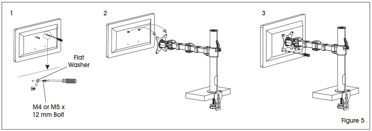
- One person should hold the monitor and align the bolt holes on the back of the monitor with the mounting plate. The second person should insert bolts into the top two holes in the mounting plate and monitor. Loosely tighten both bolts.NOTE: For 100 x 100 mm VESA hole pattern, bolts can be inserted into the top holes in back of monitor and lowered into mounting plate for easier attachment.
- While one person continues to hold the monitor, the second person should insert bolts into the bottom two holes in the mounting plate and monitor. Then, fully tighten all four bolts.
ADJUSTING MONITOR AND CABLE MANAGEMENT
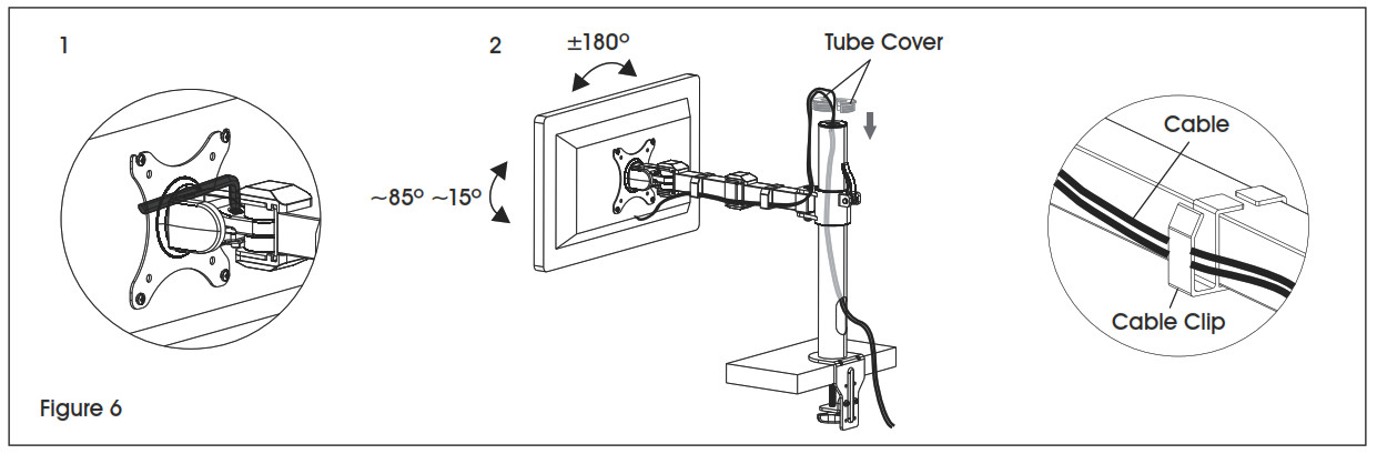
- If the monitor is difficult to adjust, use a 5 x 5 mm Allen wrench (G) to loosen bolts at hinges of monitor arm and mounting plate as needed. (See Figure 6)
- Cables can be managed by running them through cable clips on monitor arm and through the openings in tube.
![]() 1-800-295-5510uline.com
1-800-295-5510uline.com
0521 IH-7618
[xyz-ips snippet=”download-snippet”]