
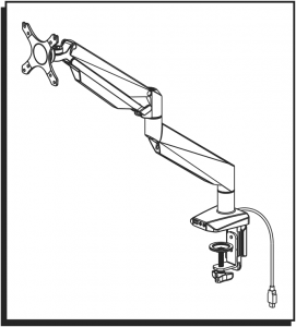
 H-7620 SINGLE MONITOR MOUNT EASY-ADJUST
 H-7620 SINGLE MONITOR MOUNT EASY-ADJUST
1-800-295-5510uline.com
TOOLS NEEDED
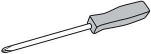

Phillips Screwdriver Two Person Assembly Required
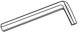
4 x 4 Allen Wrench (G) 5 x 5 Allen Wrench (H) (included)
PARTS
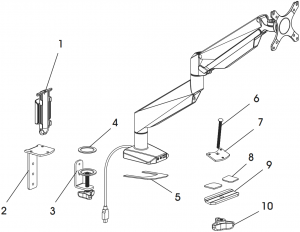
# DESCRIPTION QTY.1 Cable Clip 12 Clamp Mounting Bracket 13 Clamp 14 Anti-Slip Foam for Clamp 15 Anti-Slip Foam for Base 16 Grommet Bolt 17 Grommet Mounting Plate 18 Anti-Slip Foam for Bottom Support 29 Bottom Support 110 Knob 1A M4 x 12 mm Bolt (Not Shown) 4B M5 x 12 mm Bolt (Not Shown) 4C M6 x 12 mm Bolt (Not Shown) 3D M6 x 10 mm Bolt (Not Shown) 2F Flat Washer (Not Shown) 8
SETUP
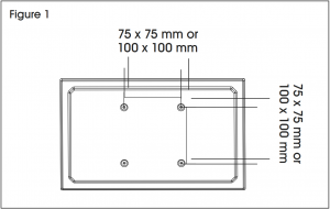
![]() NOTE: Make sure the monitor has a VESA hole pattern of 75 x 75 mm or 100 x 100 mm. (See Figure 1)
NOTE: Make sure the monitor has a VESA hole pattern of 75 x 75 mm or 100 x 100 mm. (See Figure 1)![]() NOTE: If the monitor is attached to a fixed base, remove monitor from base.
NOTE: If the monitor is attached to a fixed base, remove monitor from base.![]() CAUTION! Be careful not to scratch the monitor screen during installation.
CAUTION! Be careful not to scratch the monitor screen during installation.
ASSEMBLY
CLAMP MOUNTING
![]() NOTE: Clamp mount is compatible with desk thickness of 3/4 - 4¾”.
NOTE: Clamp mount is compatible with desk thickness of 3/4 - 4¾”.
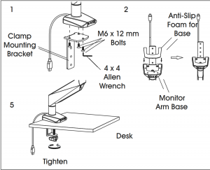
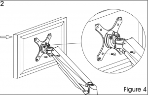
- Attach clamp mounting bracket (2) to bottom of monitor arm base using M6 x 12 mm bolts (C) and 4 x 4 Allen wrench (G). (See Figure 2)
- Apply anti-slip foam for base (5) to bottom of monitor arm base.
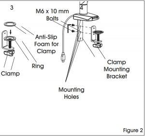
- Apply anti-slip foam for clamp (4) over ring on clamp (3).
- Attach clamp (3) to the clamp mounting bracket (2) using M6 x 10 mm bolts (D) and 4 x 4 Allen wrench (G). NOTE: Select the appropriate mounting holes based on the thickness of the desk.
- Place clamp mounting bracket and clamp over desk and fully tighten knob.
GROMMET MOUNTING
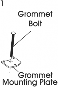
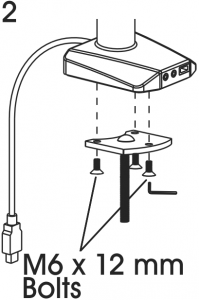
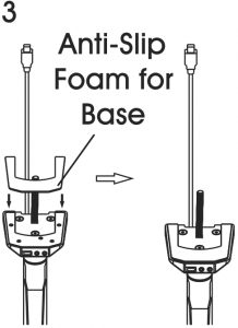
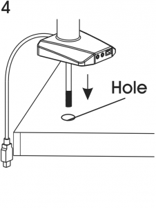
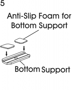
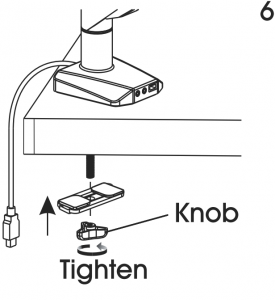
Figure 3
![]() NOTE: For grommet mounting, hole in desk must be 3/8 – 2¾”.
NOTE: For grommet mounting, hole in desk must be 3/8 – 2¾”.![]() NOTE: Grommet mount is compatible with desk thickness of 1 - 37/8”.
NOTE: Grommet mount is compatible with desk thickness of 1 - 37/8”.
- Insert grommet bolt (6) through center of grommet mounting plate (7); counterbore side down. (See Figure 3)
- Attach grommet mounting plate (7) to bottom of monitor arm base using M6 x 12 mm bolts (C) and 4 x 4 Allen wrench (G).
- Apply anti-slip foam for base (5) to bottom of monitor arm base.
- Insert grommet bolt (6) into hole of desk.
- Apply anti-slip foam for bottom supports (8) to bottom support (9).
- Thread grommet bolt (6) through bottom support (9) and attach knob (10) to end of bolt. Fully tighten knob.
ATTACHING MONITOR
![]() NOTE: Two-person assembly is required for this step.
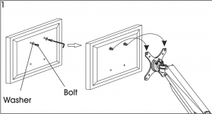
NOTE: Two-person assembly is required for this step.![]() NOTE: Depending on size of holes, use either M4 x 12 mm bolts (A) or M5 x 12 mm bolts (B). If holes are not deep enough, add flat washers (F) to bolts to ensure a tight fit.
NOTE: Depending on size of holes, use either M4 x 12 mm bolts (A) or M5 x 12 mm bolts (B). If holes are not deep enough, add flat washers (F) to bolts to ensure a tight fit.
1. One person should hold the monitor and align the bolt holes on the back of the monitor with the mounting plate. The second person should insert bolts into the top two holes in the mounting plate and monitor. Loosely tighten both bolts. (See Figure 4)
![]() NOTE: For 100 x 100 mm VESA hole pattern, bolts can be inserted into the top holes in back of monitor and lowered into mounting plate for easier attachment.
NOTE: For 100 x 100 mm VESA hole pattern, bolts can be inserted into the top holes in back of monitor and lowered into mounting plate for easier attachment.
2. While one person continues to hold the monitor, the second person should insert bolts into the bottom two holes in the mounting plate and monitor. Then, fully tighten all four bolts.
ADJUSTING MONITOR
![]() NOTE: Easy-adjust monitor includes a built-in counterweight system for free range of motion. Arm or mount may need to be adjusted to allow monitor to stop at desired position.
NOTE: Easy-adjust monitor includes a built-in counterweight system for free range of motion. Arm or mount may need to be adjusted to allow monitor to stop at desired position.
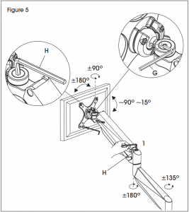
- To adjust the counterweight, use 5 x 5 Allen wrench (H) on bolt above middle joint. Turn towards “-” if monitor raises when released. Turn towards “+” if the monitor lowers when released. Adjust until mount can be stopped at desired position. (See Figure 5)
- To adjust the tilt function, use 5 x 5 Allen wrench (H) and 4 x 4 Allen wrench (G) on bolts near mounting plate. (See Figure 5)
CABLE MANAGEMENT
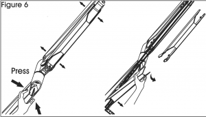
- Press both sides of cable cover and pull off to remove. (See Figure 6)
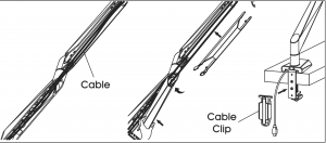
- Run cables along monitor arm and reattach cable cover over cables.
- Attach cable clip (1) to back of clamp mounting bracket (2). Run cables through cable clip for a clean appearance.
1-800-295-5510uline.com
0521 IH-7620
[xyz-ips snippet=”download-snippet”]