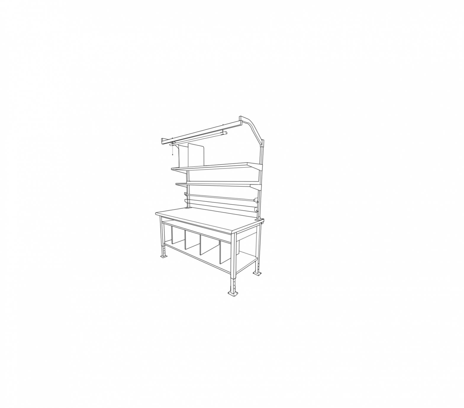
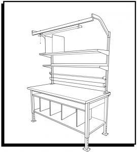
ULINE H-7630,H-7631 Packing Station
TOOLS NEEDED
|
|
|
|
|
|
|
|
 Electric Drill
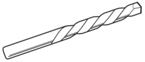 1/4″ Drill Bit
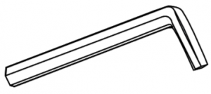 Allen Wrench (included)
 Phillips Head Drill Bit
 Phillips Screwdriver
 10 mm Wrench13 mm Wrench17 mm Wrench
PARTS

![]() CAUTION! Some parts may have sharp edges. Care must be taken when handling various pieces to avoid injury. For your safety, wear a pair of work gloves when assembling.
CAUTION! Some parts may have sharp edges. Care must be taken when handling various pieces to avoid injury. For your safety, wear a pair of work gloves when assembling.![]() NOTE: Hardware packs are included in shelf and frame packaging. Pack may include more hardware than needed.
NOTE: Hardware packs are included in shelf and frame packaging. Pack may include more hardware than needed.
|
# |
DESCRIPTION |
60 AND 7211 QTY. |
|
1 |
Leg |
2 |
|
2 |
Adjustable Foot |
4 |
|
3 |
Frame Support Bar |
2 |
|
4 |
411 High Storage Shelf |
1 |
|
5 |
Storage Shelf Support Bracket |
2 |
|
6 |
Full Depth Bottom Shelf |
1 |
|
7 |
Bottom Shelf Support Bar |
2 |
|
8 |
Bottom Shelf Divider |
4 |
|
9 |
Upright |
2 |
|
10 |
Tabletop |
1 |
Hardware Kit
|
|
 M6 x 15 Hex Bolt x 4 M6 x 15 Hex Bolt x 4 |
 M10 x 65 Hex Bolt x 12 M10 x 65 Hex Bolt x 12 |
|
|
|
|
|
|
|
|
|
|
|
|
|
 M8 x 40 Hex Bolt x 12
 M6 Phillips Head Bolt x 16
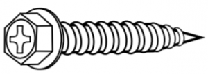 Wood Screw*
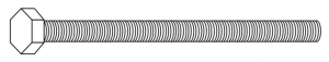 M6 x 70 Hex Bolt x 8
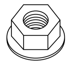 M6 Flange Nut x 28
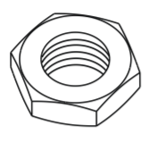 M10 Nut x 12
 M8 Nut x 4
 Flat Washer x 8
ASSEMBLY
LEGS AND FRAME ASSEMBLY
![]() NOTE: Table tops add 11/2– 1¾” depending on top purchased.
NOTE: Table tops add 11/2– 1¾” depending on top purchased.
- Flip legs (1) upside down. Place adjustable feet (2) into legs and slide to desired height. Fasten adjustable feet to legs with two M10 x 65 hex bolts and two M10 nuts per adjustable foot using a 17 mm wrench. (See Figure 1)

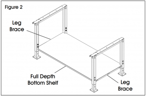
- Turn legs upright and spread apart to accommodate full depth bottom shelf. Place full depth bottom shelf (6) across leg braces. (See Figure 2)
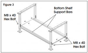
- While bottom shelf is sitting on leg braces, slide two bottom shelf support bars (7) underneath shelf and line them up with outer holes in leg brace and shelf. Fasten support bars to shelf and leg brace with four M8 x 40 hex bolts per support bar using a 13 mm wrench. Fasten center of leg brace and shelf together with four M8 x 40 hex bolts and M8 nuts using a 13 mm wrench. Do not tighten fully. (See Figure 3)
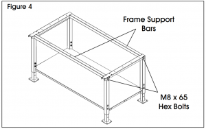
- Position frame support bars (3) so that the larger holes are facing down. Line up with legs. Fasten support bars to legs with four M8 x 65 hex bolts per leg using a 13 mm wrench. (See Figure 4)

TOP ASSEMBLY
- To attach tabletop (10) onto frame assembly, place tabletop on a smooth, non-marring surface with top side facing down.
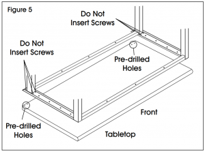
- Rotate assembled frame upside down and line up two pre-drilled holes on back corners of table top. Do not insert screws into these two holes and the two holes in front of them at this time. (See Figure 5)
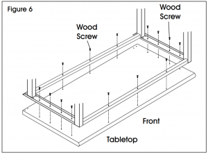
- Using all other hole locations in frame as a template, drill 3/4″ deep pilot holes into tabletop using a 3/16″ drill bit. Using 14 (16 for 72″ table) wood screws and a drill with a Phillips head drill bit, attach frame to underside of tabletop in these new pilot holes. (See Figure 6)NOTE: Additional pre-drilled holes in tabletop are used for a different product and will not align with this frame. You must pre-drill your own pilot holes.NOTE: Wood screws for front and back of frame are optional but provide more support.
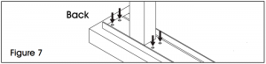
- Using a 1/4″ drill bit, drill four holes all the way through tabletop in hole locations shown in Figure 7. They should line up with holes in back of leg. (See Figure 7)NOTE: These will be used to attach uprights later.
- Carefully set table upright and recheck all screws for tightness.
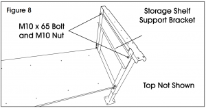
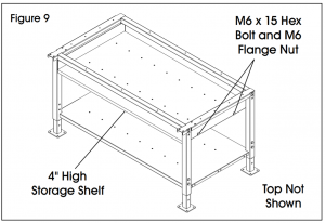
- Place two storage shelf support brackets (5) onto inside of legs with lip side facing down and inside frame. Fasten each support bracket to legs with two M10 x 65 hex bolts and two M10 nuts using a 17 mm wrench. (See Figure 8)
- Slide 4″ high storage shelf (4) onto lip of storage shelf support brackets. Line up two holes located on side of shelf with two holes in support brackets. Fasten shelf to support brackets with four M6 x 15 hex bolts and four M6 flange nuts using a 10 mm wrench. (See Figure 9)NOTE: If 4″ shelf is difficult to slide in, loosen bolts.
- Recheck and tighten all bolts.
BOTTOM SHELF DIVIDER ASSEMBLY
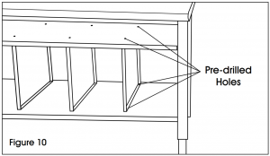
- Four bottom shelf dividers (8) are included with packing station. To attach, slide shelf dividers in-between full depth bottom shelf and 4″ high storage shelf and line them up with two pre-drilled holes in each shelf. Fasten each divider with four M6 Phillips head bolts and four M6 flange nuts using a Phillips screwdriver and 10 mm wrench. (See Figure 10)
UPRIGHT ASSEMBLY
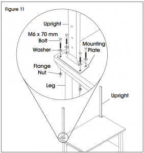
- Position upright (9) on back corner of tabletop. Mounting plate should be positioned directly over the previously drilled holes. Fasten four M6 x 70 hex bolts and flat washers through uprights, tabletop and legs using 10 mm wrench. Secure with four M6 flange nuts on underside of table. (See Figure 11)
OPTIONAL ACCESSORIES
![]() NOTE: The following products are optional accessories. Mounting hardware is included with each accessory
NOTE: The following products are optional accessories. Mounting hardware is included with each accessory

|
# |
DESCRIPTION |
Q TY. |
|
1 |
Bin Rail |
1 |
|
2 |
Monitor Arm |
1 |
|
3 |
Reel Holder Bracket |
2 |
|
4 |
Reel Holder |
1 |
|
5 |
12″ Deep Top Shelf Bracket |
2 |
|
6 |
12″ Deep Top Shelf |
1 |
|
7 |
12″ Deep Top Shelf Divider |
* |
|
8 |
16″ Deep Box Shelf Bracket |
2 |
|
9 |
16″ Deep Box Shelf |
1 |
|
10 |
16″ Deep Box Shelf Divider |
6 |
|
11 |
LED Shop Light |
1 |
|
12 |
Light Bracket |
2 |
|
13 |
Light Steel Beam |
1 |
|
14 |
“S” Hooks |
2 |
|
15 |
Tabletop Power Strip |
1 |
|
16 |
Tape Gun Holder |
1 |
|
17 |
Fan |
1 |
|
18 |
6″ Fan Mounting Bracket |
1 |
|
19 |
10″ Fan Mounting Bracket |
1 |
|
20 |
Fan Upright Mounting Bracket |
1 |
| Tape Gun Upright Mounting Bracket (Not Shown) |
1 |
BIN RAIL ASSEMBLY
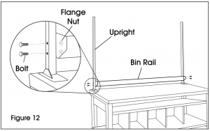
- Line up bin rail (1) with uprights at desired height.
- Secure to uprights with four 11/2” bolts and flange nuts. (See Figure 12)
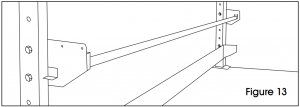
REEL HOLDER ASSEMBLY
- Line up reel holder brackets (3) with uprights at desired height.2. Secure to uprights with four M6 x 40 mm hex bolts and flange nuts. (See Figure 13)
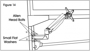
MONITOR ARM ASSEMBLY
- Line up monitor arm mounting bracket (2) with uprights at desired height.
- Secure to uprights with two M6 x 35 mm or M6 x 50 mm Allen head bolts, two small flat washers and two hex nuts using an Allen wrench and 10 mm wrench. (See Figure 14)
ATTACHING MONITOR
![]() NOTE: Make sure monitor has a VESA hole pattern of 100 x 100 mm or 75 x 75 mm. (See Figure 15).
NOTE: Make sure monitor has a VESA hole pattern of 100 x 100 mm or 75 x 75 mm. (See Figure 15).![]() NOTE: If monitor is attached to a fixed base, remove monitor from base.
NOTE: If monitor is attached to a fixed base, remove monitor from base.![]() CAUTION! Be careful not to scratch screen during installation.
CAUTION! Be careful not to scratch screen during installation.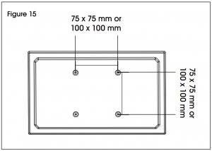
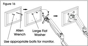
- Easy-adjust monitor mount includes a built-in counterweight system for free-range motion. Arm in mount may need to be adjusted to allow monitor to stop at desired position. Attach monitor to plate. (See Figure 16)
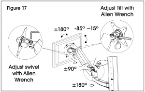
- To adjust the counterweight, use 5 x 5 Allen wrench on screw above middle joint. Turn towards “–” if monitor raises up. Turn towards “+” if monitor lowers. Adjust until mount can be stopped at desired position. (See Figure 17)
CABLE MANAGEMENT
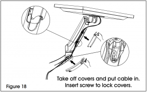
- To remove covers, use a Phillips head screwdriver to unscrew the two screws securing covers to the monitor arm. This allows user to slide cables through covers. Once complete, re-secure the covers to the monitor arm using the Phillips head screws. (See Figure 18)
12″ DEEP TOP SHELF ASSEMBLY
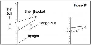
- Line up shelf brackets (5) with uprights at desired height.
- Secure to uprights with four 11/2” bolts and flange nuts. (See Figure 19)
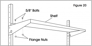
- Place shelf (6) on brackets. Install to brackets with four 5/8″ bolts and flange nuts. (See Figure 20)
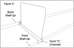
12″ DEEP TOP SHELF DIVIDER ASSEMBLY
- Line up front “C” channel of divider (7) with front lip of top shelf. Insert divider into front lip at angle. Once in place, allow divider to drop and magnetize to back shelf lip. (See Figure 21)
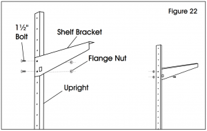
16″ DEEP BOX SHELF ASSEMBLY
- Line up shelf brackets (8) with uprights at desired height.
- Secure to uprights with four 11/2” bolts and flange nuts. (See Figure 22)
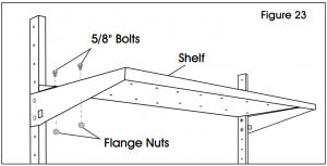
- Place shelf (9) on brackets. Install to brackets with four 5/8″ bolts and flange nuts. (See Figure 23)
16″ DEEP BOX SHELF DIVIDER ASSEMBLY
- Six box shelf dividers (10) are included with box shelf. To attach, line up front and rear pre-drilled holes on top of shelf. Fasten each divider with two Phillips head bolts and two M6 flange nuts using a Phillips screwdriver and 10 mm wrench. (See Figure 24)

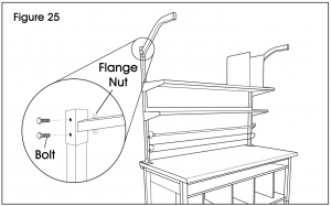
LIGHT KIT ASSEMBLY
- Line up light brackets (12) with uprights at desired height.
- Secure to uprights with four 2″ bolts and flange nuts. (See Figure 25)
- Place light steel beam (13) at desired depth underneath brackets. Fasten to brackets with two 4¾” bolts and flange nuts. (See Figure 26)
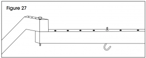
- Place two “S” hooks (14) at desired mounting points along the steel beam and secure with two flange nuts. (See Figure 27)
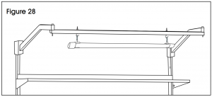
- Attach hanging chains to LED shop light (11) and mount to “S” hooks. (See Figure 28)

TABLETOP POWER STRIP ASSEMBLY
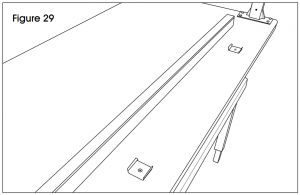
- Choose desired location for power strip (15). Place two supplied mounting clips roughly 32″ apart (clip side up). Using an electric drill, fasten to tabletop with two supplied wood screws. (See Figure 29)
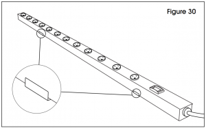
- Secure power strip by snapping into the mounting clips. (See Figure 30)
TAPE GUN HOLDER
![]() NOTE: Tape Gun holder can be attached to uprights or bin rail.
NOTE: Tape Gun holder can be attached to uprights or bin rail.
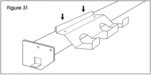
- If attaching to bin rail, no assembly is needed. Place the back folded lip of the bracket over the bin rail. Push down to ensure it is set firmly in place. (See Figure 31)
- If attaching to uprights, slide tape gun upright bracket underneath tape gun holder and align the holes in the bracket to the holes on top of the holder. Attach with two M5 x 10 mm pan head screws and two M5 flange nuts using a Phillips screwdriver and 8 mm wrench. (See Figure 32)
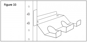
- Align gun holder and upright bracket with uprights at desired height.
- Secure to uprights with two M6 x 40 mm hex bolts and two M6 flange nuts. (See Figure 33)

FAN ASSEMBLY
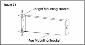
![]() NOTE: Fan comes with 6″ and 10″ long bracket. Choose desired bracket based on application.
NOTE: Fan comes with 6″ and 10″ long bracket. Choose desired bracket based on application.
- Slot 6″ or 10″ fan mounting bracket between opening in fan upright mounting bracket. Align holes of each bracket and attach using two M6 x 12 mm hex bolts and two M6 flange nuts. (See Figure 34)
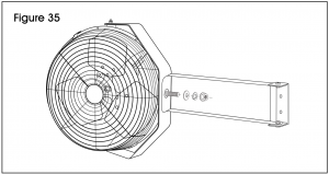
- Align hole on the opposite end of fan mounting bracket to the hole on the crescent fan bracket. Attach using M12 x 20 mm hex bolt, M12 washer, M12 lock washer and M12 hex nut. (See Figure 35)
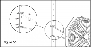
- Align fan assembly with uprights at desired height.
- Secure to uprights with two M6 x 40 mm hex bolts and two M6 flange nuts. (See Figure 36)

1-800-295-5510www.uline.com
[xyz-ips snippet=”download-snippet”]