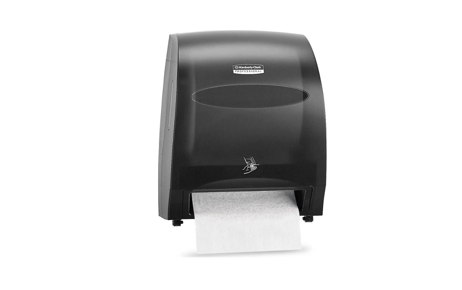
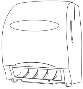
ULINE H-7883 Automatic Paper Towel Dispenser User Guide
TOOLS NEEDED
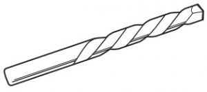
- Electric Drill

- 1/4″ Drill Bit
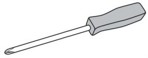
- Phillips Screwdriver
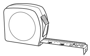
- Tape Measure
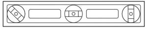
- Level

PARTS
- Dispenser x 1
- Dispenser Key x 1
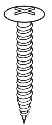
- Screw x 4
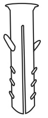
- Anchor x 4
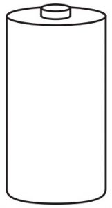
- D-Cell Battery x 4
MOUNTING
NOTE: Recommended mounting height is 48″ from the floor to bottom of dispenser.
NOTE: Ensure that proper mounting hardware is used for appropriate wall composition as enclosed hardware may not be compatible with your wall surface.
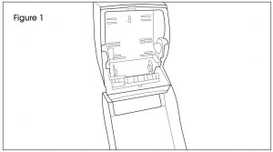
- Open dispenser cover by inserting the key into the top of the dispenser and holding dispenser to ideal mounting place on wall. (See Figure 1)
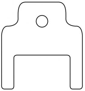
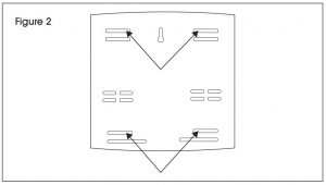
- Mark the holes on the wall where screws will be inserted. (See Figure 2)
- Set dispenser aside and drill into wall at four marked locations with an appropriate drill bit. (See Figure 3) Insert wall anchors if necessary.
- Hold dispenser to wall so holes in dispenser align with previously drilled holes in wall. Insert four screws.

LOADING
LOADING THE DISPENSER WITHOUT A STUB ROLL
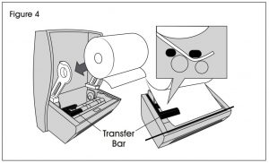
- Open cover and load paper roll with paper “tail” unwinding from back of roll. Place paper “tail” over the back transfer bar arm and under the front transfer bar arm. (See Figure 4)
- Firmly close dispenser. The unit is ready to dispense at the factory set nominal 11-inch paper length (it takes about three dispenses to self-adjust to the nominal paper length). (See Figure 4)
LOADING THE DISPENSER WITH A STUB ROLL
- When the main roll is approximately 2.6″ in diameter (60′ remaining), move the stub roll to the lower roll holders. (See Figure 5)
- Lift the transfer bar and place the paper under both the front and back arms. The paper should dispense between the two white rollers.
- Load the new towel roll into the upper roll holders so that the paper feeds down from the back. (See Figure 6)
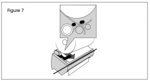
- Lift the transfer bar and place the leading edge of the new paper roll under the front transfer bar arm and on top of the existing paper sheet. Release the transfer bar. (See Figure 7)
- Leave some slack in the main roll to ensure proper transfer.
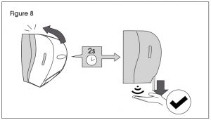
- Firmly close dispenser and wait two seconds. (See Figure 8)
- The stub roll will continue to dispense paper until the last 15 feet, at which time the main roll will begin to feed. During this transition both rolls will feed paper until the stub roll is empty


OPERATION
OPENING THE COVER
Key is taped to back of dispenser.
- Insert forked end of key into two slots at top of cover.
- Push down on key and pull forward on cover.NOTE: Opening the cover removes battery power from control circuit.
INSTALLING BATTERIES
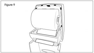
- Open cover. The battery compartment is located at the front lip of the dispenser. The cover to the battery compartment is removed by pushing the left hand tab inward and lifting up. (See Figure 9)
- Insert four “D”-size alkaline batteries with “LR20” designation. (Battery orientation is embossed on compartment.)NOTE: We do not recommend using rechargeable “D”-size batteries
- Red LED will flash one time after the batteries are installed and the cover is closed to indicate that the unit is powered on and initialized.
- When battery power is low, the LED will flash once every 1.5 seconds continuously when the batteries need replacement.
PAPER SAVER TECHNOLOGY FEATURE
This dispenser is equipped with patented Paper Saver technology.
The Paper Saver technology decreases the second sheet of paper by 10% when the dispenser is activated within three seconds of a previous dispense.
TROUBLESHOOTING
| OPERATING ISSUE | RECOMMENDATIONS |
| OPERATING ISSUE RECOMMENDATIONS Unit will not dispense. | Ensure cover is closed and securely latched. Replace batteries if LED indicator light is flashing. Make sure batteries are installed and oriented properly. Remove and re-install batteries. |
Contact: 1-800-295-5510Website: uline.com
[xyz-ips snippet=”download-snippet”]