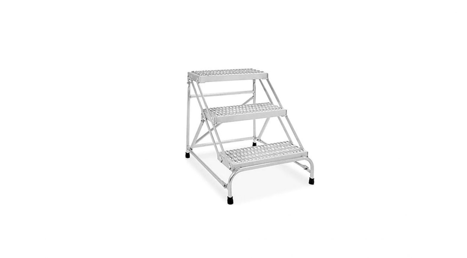
ULINE H-7906 3-Step Aluminum Step Stand Instruction Manual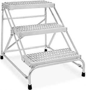
TOOLS NEEDED
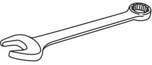
- 9/16″ (14 mm) Wrench

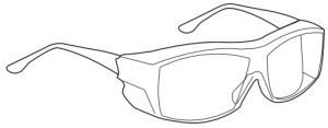
- Safety Glasses
PARTS
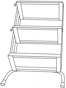
- Steps x 1
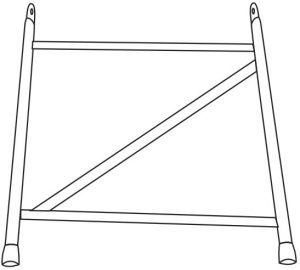
- Back Panel x 1
- Short Brace x 2
- Long Brace x 2
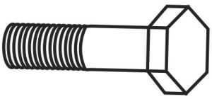
- 3/8-16 x 1/” Hex Head Cap Screw x 6 (Included)
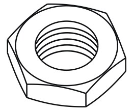
- 3/8-16 Hex Nut x 6 (Included)
ASSEMBLY INSTRUCTIONS
WARNING! Please read and save these instructions. Read carefully before attempting to assemble, install, operate or maintain the product described. Protect yourself and others by observing all safety information. Failure to comply with instructions could result in personal injury and/or death. Retain instructions for future reference. Assembly and installation of the 3-Step Stand can be inherently dangerous. Take all precautions necessary during assembly and installation.
DANGER! Death or serious injury may occur if improperly assembled or used.
- Assembly can be dangerous.
- Read all instructions thoroughly before assembling and using.
- Take necessary precautions during the assembly process.
- Do not fully tighten mounting bolts until instructed to do so.
- Remove the step stand from the packaging and place on a level surface.NOTE: If any parts appear damaged in any way, STOP, do not proceed with assembly and contact Uline.
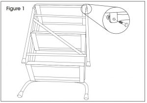
- Attach back panel to top of steps with 3/8-16 x 1/” hex head cap screws and hex nuts. Do not fully tighten. (See Figure 1)
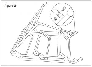
- Connect the end of long brace to front leg using 3/8-16 x 1/” hex head cap screw and hex nut. (See Figure 2)
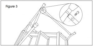
- Pivot the rear panel upward and pivot the long bottom brace upward. Connect the other end of long bottom brace to rear panel lug using the 3/8-16 x 1/” hex head cap screw. Do not attach hex nut. (See Figure 3)
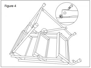
- Connect the short brace to middle panel lug using 3/8-16 x 1/” hex head cap screw and hex nut. (See Figure 4)
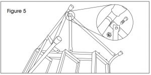
- Pivot short brace up and connect to rear panel lug over the long bottom brace, using the same hex head cap screw. The short brace will be installed over the long brace. Place hex nut onto hex head cap screw where the braces connect to the rear panel lug. Do not fully tighten. (See Figure 5)
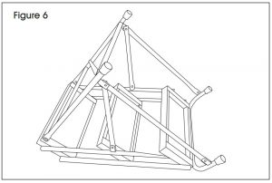
- Repeat steps three through eight for the remaining long bottom and short middle braces on opposite side. (See Figure 6)DANGER! Do not use step stand unless all components and the cap screws are in place and nuts are securely tightened.
- Turn the step stand over onto a level surface. (See Figure 7)
- Tighten all of the hex nuts onto hex head cap screws. All of the braces and connections should be tight and not loose.DANGER! Inspect the step stand for any permanent deformation, corrosion, degradation or any condition impairing protective capability. If any of these conditions are suspected, remove from service with warnings prohibiting use prominently displayed on the step stand until step stand can be replaced.
 DANGER! Do not use step stand unless all components and the cap screws are in place and nuts are securely tightened.
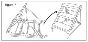
Contact: 1-800-295-5510 Website: uline.com
[xyz-ips snippet=”download-snippet”]