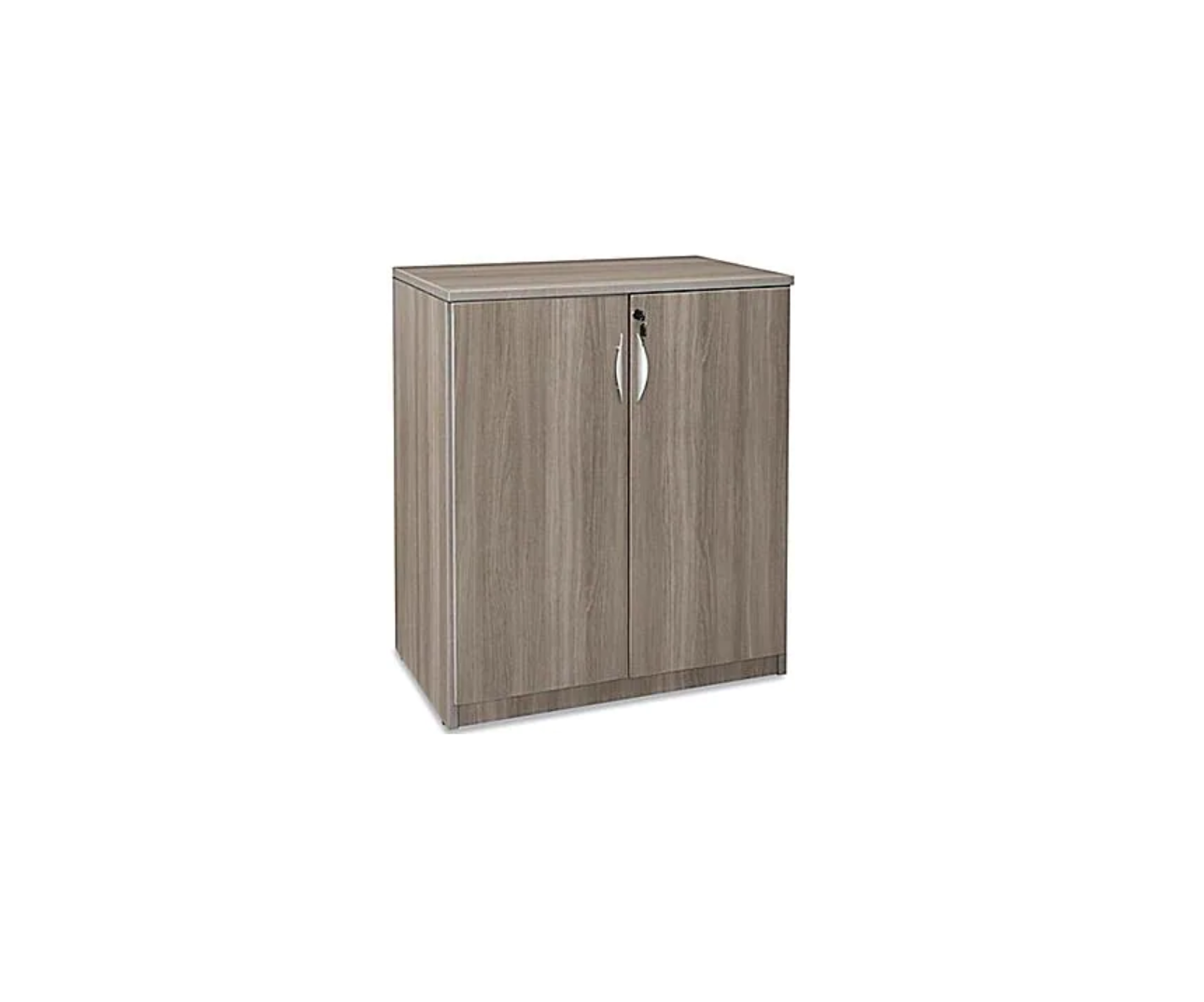
ULINE H-9188 2 Door 42″ Office Storage Cabinet Installation Guide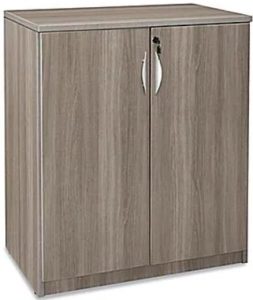
TOOLS NEEDED
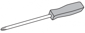
- Phillips Screwdriver

- Drill (Optional)
- 5/16″ Drill Bit (Optional)
- Two Person Assembly Recommended


PARTS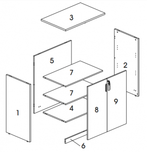
| # | DESCRIPTION | QTY |
| 1 | Left Side Panel | 1 |
| 2 | Right Side Panel | 1 |
| 3 | Top Panel | 1 |
| 4 | Bottom Panel | 1 |
| 5 | Back Panel | 1 |
| 6 | Skirt Panel | 1 |
| 7 | Shelf | 2 |
| 8 | Left Door | 1 |
| 9 | Right Door | 1 |


ASSEMBLY
![]() NOTE: Assemble unit on a smooth, non-marring surface to prevent scratching. Check that all parts are included.
NOTE: Assemble unit on a smooth, non-marring surface to prevent scratching. Check that all parts are included.
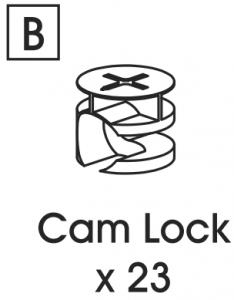
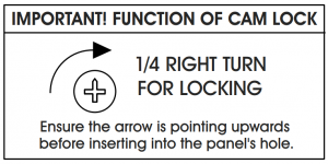
![]() IMPORTANT! Turn cam lock 1/4 to the right to lock. Ensure the arrow is pointing to edge of panel before inserting into the panel’s hole.
IMPORTANT! Turn cam lock 1/4 to the right to lock. Ensure the arrow is pointing to edge of panel before inserting into the panel’s hole.
![]() MPORTANT! Cam lock pins must be tightened once inserted into panel. To tighten cam lock pins, grasp lower part of cam lock pin and tighten using a Phillips head screwdriver.
MPORTANT! Cam lock pins must be tightened once inserted into panel. To tighten cam lock pins, grasp lower part of cam lock pin and tighten using a Phillips head screwdriver.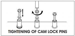
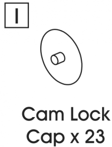
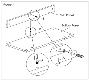
- Insert cam lock pin (A) into bottom panel. Insert cam lock (B) into skirt panel. Attach skirt panel and tighten cam lock using a Phillips head screwdriver. (See Figure 1)NOTE: Cam lock caps (I) can be applied once cam locks are tightened for a finished look.
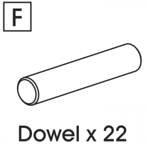
- Insert cam lock pins (A) and dowels (F) into back panel. Insert cam locks (B) into bottom panel. Attach bottom panel and tighten cam locks using a Phillips head screwdriver. (See Figure 2)
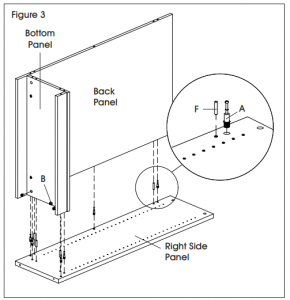
- Insert cam lock pins (A) and dowels (F) into right side panel. Insert cam locks (B) into bottom panel, back panel and skirt panel. Attach bottom and back panels and tighten cam locks using a Phillips head screwdriver. (See Figure 3)
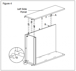
- Insert cam lock pins (A) and dowels (F) into left side panel. Insert cam locks (B) into bottom panel, back panel and skirt panel. Attach bottom and back panels and tighten cam locks using a Phillips head screwdriver. (See Figure 4)
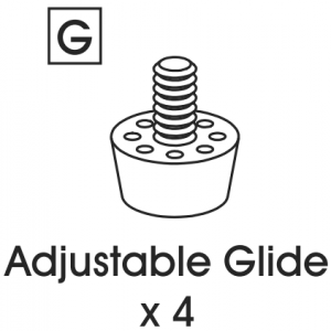
- Insert adjustable glides (G) into bottom of side panels. (See Figure 4)
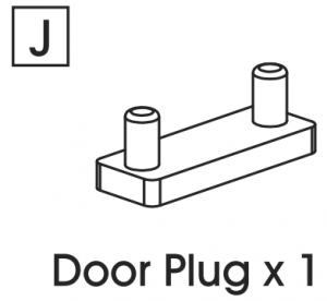
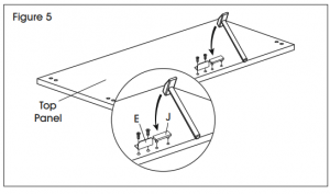
- Align holes on L-bracket (E) with pre-drilled holes in top panel. Insert two M3 x 12 mm screws and attach using a Phillips head screwdriver or drill. Align holes on plug (J) with pre-drilled holes in top panel and gently tap with a rubber mallet to insert. (See Figure 5)
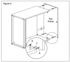
- Insert cam lock pins (A) and dowels (F) into top panel. Insert cam locks (B) into back panel, right side panel and left side panel. Attach top panel and tighten cam locks using a Phillips head screwdriver. (See Figure 6)
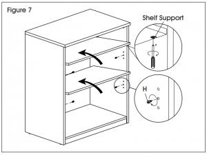
- Place cabinet upright. Insert shelf dowels (H) into side panels. Place shelves inside cabinet and ensure shelf supports lower onto shelf dowels. Tighten shelf supports in underside of shelves for a secure fit. (See Figure 7)
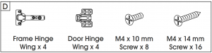
- Place left door and right door panels on a smooth, non-marring surface to prevent scratching. Snap door hinge wing and frame hinge wing together. Align holes in hinge (D) with pre-drilled holes in door panel. Insert two M4 x 10 mm screws and tighten using a Phillips head screwdriver or drill. Repeat for three remaining hinges. (See Figure 8)
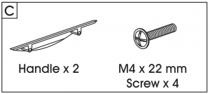
- Attach handles (C) to the outside of the door panels using M4 x 22 mm screws and a Phillips head screwdriver. (See Figure 8)
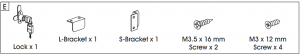
- Align holes on S-bracket (E) with pre-drilled holes on left door. Insert two M3 x 12 mm screws and attach using a Phillips head screwdriver or drill. (See Figure 9)
- Align holes on lock (E) with pre-drilled holes on right door. Insert two M3.5 x 16 mm screws (E) and attach using a Phillips head screwdriver or drill. (See Figure 9)
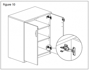
- Using two people, hold door panel in line with side panel. Attach hinge to side panel using four M4 x 14 mm screws. Repeat for three remaining hinges. (See Figure 10)
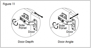
- Once door panels are attached, each hinge may need to be adjusted to align the doors. To adjust the depth of the doors, tighten or loosen the rear screw in the hinge. To adjust the angle of the doors, tighten or loosen the center screw in the hinge. (See Figure 11)
 NOTE: Cam lock caps (I) can be applied once cam locks are tightened for a finished look.
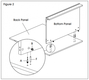


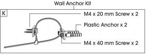
ANCHOR
Attach one bracket of wall anchor (K) to back of top panel using two M4 x 20 mm screws. Mark holes on wall where plastic anchors are to be located. Drill holes using 5/16″ drill bit. Mount opposite bracket of wall anchor to wall with two M4 x 40 mm screws and two M8 x 36 mm plastic anchors. Tighten cable tie to prevent tipping. (See Figure 12)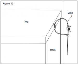
 1-800-295-5510Web: uline.com
[xyz-ips snippet=”download-snippet”]