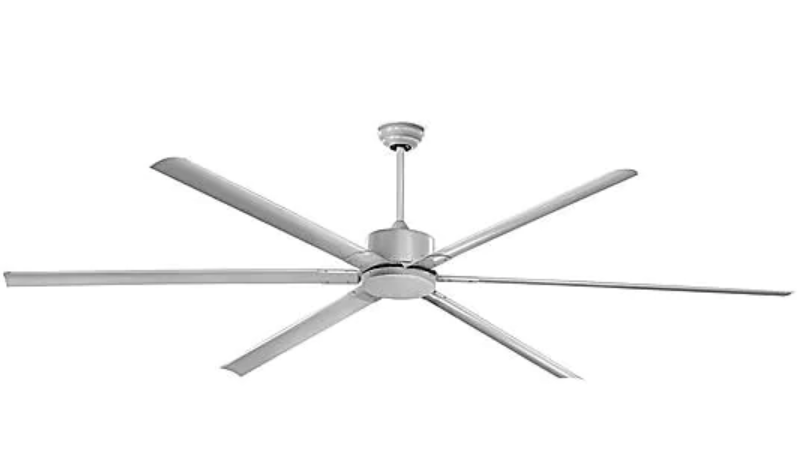
ULINE Industrial Ceiling Fan User Manual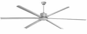
TOOLS NEEDED
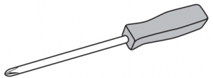
- Phillips Head Screwdriver

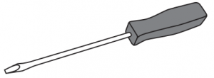
- Flat Head Screwdriver
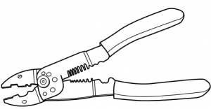
- Wire Cutters
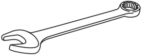
- 5/16″ Wrench
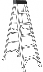
- Ladder
PARTS
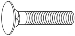
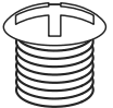
- Carriage Bolt x 24
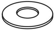
- Flat Washer x 24
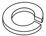
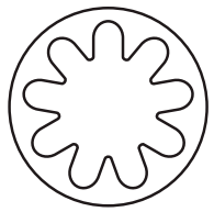
- Lock Washer x 42
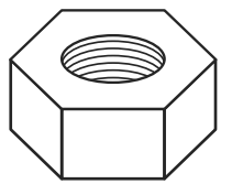
- Hex Nut x 24
- Rubber Gasket x 2
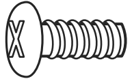
- Phillips Head Screw x 18
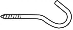
- J-Hook x 1
- S-Hook x 1
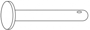
- Yoke Bolt x 1
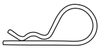
- Cotter Pin x 1
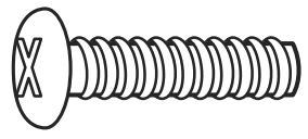
- Jam Screw x 1
- Housing Screw x 3
- Housing Star Washer * 3
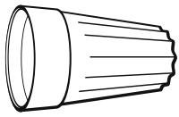
- Wire Nut * 3 (not drovided)

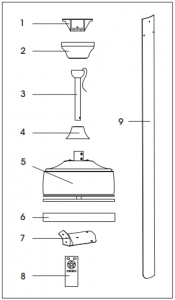
FAN COMPONENT LIST
| # | DESCRIPTION | QTY. |
| 1 | Mounting Bracket | 1 |
| 2 | Canopy | 1 |
| 3 | Downrod Assembly | 1 |
| 4 | Yoke Cover | 1 |
| 5 | Fan Motor Assembly | 1 |
| 6 | Housing Cover | 1 |
| 7 | Blade Bracket | 6 |
| 8 | Remote Control | 1 |
| 9 | Fan Blade | 6 |
SAFETY
- Turn off power at main electrical service box before starting
- Electrical connections must comply with local code ordinances, national electrical codes, CEC, NEC and ANSI/NFPA
- Ensure installation site allows fan blades to rotate freely without any
- When mounting fan on a ceiling outlet box, use an approved ceiling fan box (UL for S. and CSA for Canada) marked “For Fan Support.” Ensure outlet box is securely installed in place such that it can support at least the fan weight.
 WARNING! To reduce risk of fire, electric shock or personal injury, mount fan only to an outlet box marked acceptable for fan support and use mounting screws provided with outlet box. Most outlet boxes commonly used for support of lighting fixtures are not acceptable for fan support and may need to be replaced. Consult a qualified electrician if in doubt.
![]() WARNING! To reduce the risk of personal injury, do not bend the blade brackets when installing the brackets, balancing the blades or cleaning the fan. Also, do not insert foreign objects between rotating fan blades.
WARNING! To reduce the risk of personal injury, do not bend the blade brackets when installing the brackets, balancing the blades or cleaning the fan. Also, do not insert foreign objects between rotating fan blades.
![]() WARNING! Mount with the lowest moving parts at least 10 feet above floor or grade level.
WARNING! Mount with the lowest moving parts at least 10 feet above floor or grade level.
![]() WARNING! All set screws must be checked and re-tightened where necessary after installation. No lubricants should be used on screws or hooks.
WARNING! All set screws must be checked and re-tightened where necessary after installation. No lubricants should be used on screws or hooks.
![]() WARNING!To reduce the risk of personal injury install the safety cable.
WARNING!To reduce the risk of personal injury install the safety cable.
![]() WARNING!Do not attach blades before hanging the fan.
WARNING!Do not attach blades before hanging the fan.
![]() NOTE: Total fan weight is 40 lbs.
NOTE: Total fan weight is 40 lbs.
MOUTING
DOWNROD
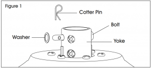
- Take out fan motor housing. Remove cotter pin, washer and bolt from yoke. (See Figure 1).
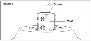
- Loosen jam screw in yoke until it is flush with the inside surface. (See Figure 2).
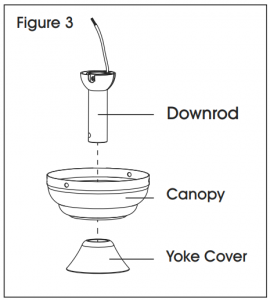
- Place downrod inside canopy and yoke (See Figure 3).
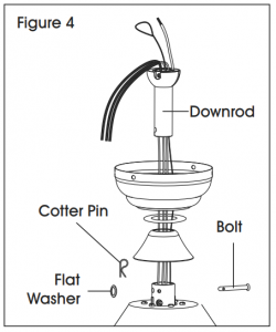
- Route wires exiting motor through yoke cover, canopy and downrod. Insert bolt through hole in Yoke and downrod. Be careful not to damage or cut fan wires. Tighen flat washer and bolt. Secure with cotter pin through hole in the end of bolt. (See Figure 4).
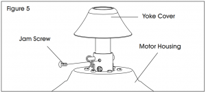
- Secure downrod in position by tightening jam Slide yoke cover down so it is flush with motor housing. (See Figure 5).
MOUNTING BRACKET
![]() WARNING! To reduce the risk of fire, electric shock or personal injury, mount to UL/CSA listed outlet box marked acceptable for fan support and use mounting screws provided with outlet box.
WARNING! To reduce the risk of fire, electric shock or personal injury, mount to UL/CSA listed outlet box marked acceptable for fan support and use mounting screws provided with outlet box.
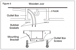
- Install the J-hook through center of outlet box and into wooden Secure mounting bracket and rubber gaskets to outlet box using outlet box screws (not provided). (See Figure 6).
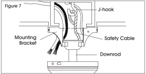
- Hang the safety cable onto the J-hook. Insert top of fan downrod into mounting (See Figure 7).
ELECTRICAL HOOK-UP
![]() CAUTION!
CAUTION!
- Green Wire – Ground
- Black Wire (Fan) – Power
- White Wire (Fan) – Common
See safety precautions on page 2 before wiring.
NOTE: After making the wire connections, ensure wires are spread apart with the grounded conductor and the equipment- grounding conductor on one side of outlet box and ungrounded conductor on other side of outlet box. Ensure the completed splices are turned upward and pushed carefully up into the outlet box.
CONNECTING THE (GREEN) GROUND WIRE
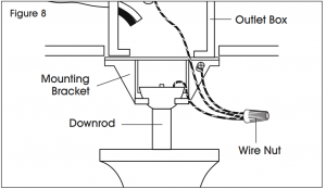
- Connect ground wire from outlet box to green wire from mounting bracket and downrod using a wire nut (not provided). (See Figure 8).NOTE: Once ground wires are connected, carefully tuck wires and wire nut into outlet box, ensuring wires are clear of downrod when positioned in mounting bracket.
CONNECTING POWER WIRES
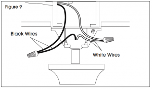
- Connect white wire from outlet box to white wire from fan using wire nut (not provided). (See Figure 9)
- Connect black wire from outlet box to black wire from fan using wire nut (not provided). (See Figure 9)
![]() NOTE: Once wires are connected, carefully tuck wires and wire nuts into outlet box, ensuring wires are clear of downrod when positioned in mounting bracket.
NOTE: Once wires are connected, carefully tuck wires and wire nuts into outlet box, ensuring wires are clear of downrod when positioned in mounting bracket.
MOUNTING FAN/CANOPY ASSEMBLY
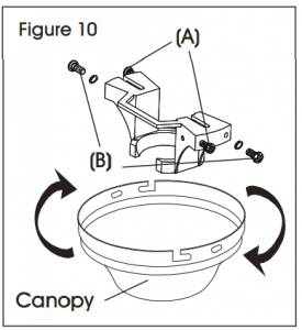
- Place two housing screws and two lock washers (A) on mounting plate that corresponds with slots in Screw in with only two turns. (See Figure 10)
- Position canopy to mounting plate, aligning slots to two housing screws and two lock washers (B) and turn to Position and tighten all screws and washers. (See Figure 10)
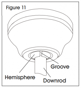
- Carefully rotate fan assembly until groove in hemisphere locks over tab of canopy assembly. (See Figures 10-11)
WARNING! Failure to seat tab in groove could cause damage to electrical wires and possible shock or fire hazard
![]() NOTE: When installing fan on sloped ceiling, ensure tab on hanger bracket faces toward top of slope. Depending on slope, a longer downrod may be required to prevent fan blades from hitting ceiling.
NOTE: When installing fan on sloped ceiling, ensure tab on hanger bracket faces toward top of slope. Depending on slope, a longer downrod may be required to prevent fan blades from hitting ceiling.
MOUNTING BLADE BRACKETS TO BLADES
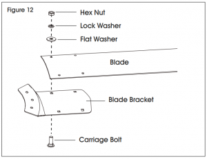
- Place one carriage bolt through blade bracket, blade, flat washer and lock washer. Attach with hex nut using 5/16″ wrench. Repeat for the three remaining mounting locations. (See Figure 12).
MOUNTING BLADES TO MOTOR
![]() WARNING! Turn off power before installing.
WARNING! Turn off power before installing.
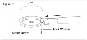
- Insert blade arm into Tighten using Phillips head screwdriver, three Phillips head screws and three lock washers. (See Figure 13).
- Slightly turn blade after installation and repeat for the remaining blades.
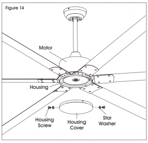
- Carefully tuck electrical wires back into housing, align housing cover with housing, and secure with three housing screws and three star washers.(See Figure 14). WARNING! Ensure that all connections, set screws and screws are securely tightened before the next step.
- To clean fixture, turn off power, wait for it to cool and wipe it with a clean, soft cloth.
REMOTE CONTROL
PROGRAMMING
|
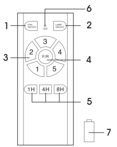
REMOTE FAN CONTROLS |
|
|
1 |
ON/OFF |
|
2 |
Lamp Short press: ON/OFF Long press: dimming (hold for 3 seconds) |
|
3 |
Speed: 1=low, 5=high |
|
4 |
Direction |
|
5 |
Timing Control |
|
6 |
LED light |
|
7 |
12V Battery |
- Turn ON supply power to fan. Within 30 seconds, press and hold FAN ON/OFF button on the remote for five seconds. Remote and fan are connected after hearing a long beep.
- If remote cannot control the fan, ensure all wiring connections are properly connected according to the instruction Ensure batteries are in correct position. Check if any similar remote controls are in use nearby and whether they work with the same frequency.
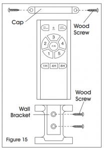
WALL BRACKET (OPTIONAL)
- Use wood screws (not provided) to secure wall bracket at desired mounting (See Figure 15).
- Place remote control into wall bracket.
- If needed, mount cap onto top of remote control using two wood screws (not provided).
TROUBLESHOOTING
|
OPERATING ISSUE |
RECOMMENDATIONS |
|
Fan will not start. |
Check wiring connection to fan.Turn power off and check fuses and circuit breakers.Turn power off and check wiring connections in switch housing. |
|
Fan sounds noisy. |
Ensure all screws in motor housing are snug. Ensure blade bracket screws are tight. Ensure wire nuts in switch housing are not rattling against wall of switch housing. If fan has a light kit, make sure switch housing screws and set screws are tight.Some fan motors are sensitive to signals from solid state variable controls. If solid state controller is used, change to an alternative control.Allow a 24-hour break-in period to eliminate most noises. |
|
Fan wobbles or shakes excessively. |
Check that all blades are screwed firmly into blade brackets. Check that blade brackets are secured firmly to motor.Check distance from tip of blades to ceiling.Check distance from blade tip to blade tip. All measurements should be equal. Loosen blade screws and re-position blade until even, then re-tighten. Check that the downrod hemisphere notch is engaged in canopy. Check that jam screws in the downrod are tightened.Ensure canopy and mounting bracket are tightened securely to wooden joist.Ensure warpage has not occurred in wooden blades. If so, contact Uline Customer Service at 1-800-295 5510 for replacement parts. |
 1-800-295-5510uline.com
[xyz-ips snippet=”download-snippet”]