
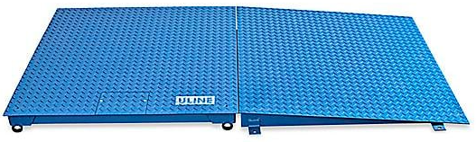
ULINE Low Profile Floor Scale
INTRODUCTION
SITE SELECTIONSelect a site for the floor scale where it is least likely to be damaged by fork trucks and other material handling devices. Floor scale load cell weighing elements are prone to overload damage caused by side impacts, falling objects and weight loads that exceed the rated capacity of the scale.Site should be:
- Level within 1/4″.
- Free from vibration.
- Dry for standard, non-washdown floor scales.
- Clean of debris.
- Out of the way of vehicle traffic patterns, unless installed in a pit while having a rated capacity that exceeds all loaded vehicle weights that could possibly drive onto or contact the scale.
The cable from the floor scale to the digital weight indicator should be run through conduit to protect it against possible damage. Running the interface cable through conduit is the best method of protection.
UNPACKING
- Inspect your shipment for damage. If you see visible signs of damage, notify carrier at once.
- Remove floor scale from the shipping pallet.
- Unpack the digital indicator. Digital indicator and power cord should be included.
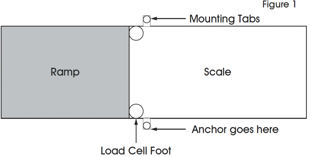
RAMP INSTALLATION (OPTIONAL)
- Set floor scale in desired location.
- Position the scale feet inside the mounting tabs. (See Figure 1)
- Anchor the ramp to the floor using two 1/2 x 3″ anchors (not included).
HEIGHT AND LEVEL ADJUSTMENTS
- Unlock the nuts on all four feet.
- Using a pry bar, lift the weight of the scale base off the scale feet.
- Make adjustments by screwing the feet counterclockwise. All four feet should make firm contact with the floor.
- Do not screw feet counterclockwise more than ten turns.
- Tighten locknuts on feet.
- Check your work.
PARTS DIAGRAM
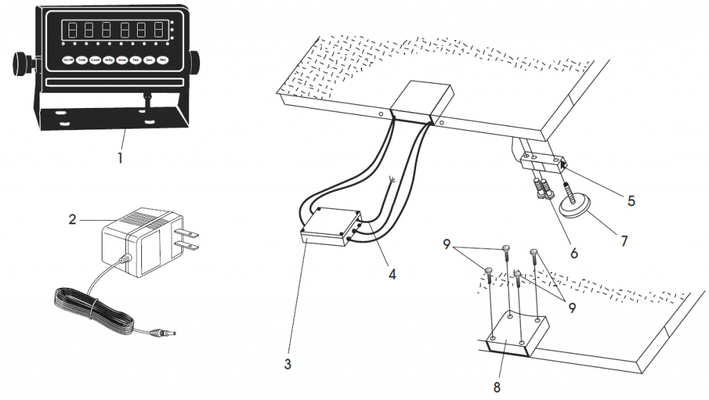
| # | DESCRIPTION | QTY. |
| 1 | LP-7510 Display Indicator Kit | 1 |
| 2 | AC Adapter | 1 |
| 3 | Junction Box with Summing Card | 1 |
| 4 | Instrument Cable for LP-7510 Display Indicator | 1 |
| 5 | Load Cell – 2,500 lb. + 5,000 lb. Capacity | 1 |
| 5 | Load Cell – 10,000 lb. Capacity | 1 |
| 5 | Load Cell – 20,000 lb. Capacity | 1 |
| 6 | Load Cell Bolt | 2 |
| 7 | Foot | 4 |
| 8 | Access Plate | 1 |
| 9 | Access Plate Screw | 4 |
| Summing Card (Not Shown) | 1 | |
| Foot Pad (Not Shown) | 1 |
ASSEMBLY
SETUP INSTRUCTIONS
NOTE: Floor scale was shipped with the four threaded leveling feet adjusted for a flat and even floor. The leveling feet are locked in place with locknuts. See page 1 for height and level adjustments.
- Plug the instrument cable connector into the digital weight indicator. This cable is located in the junction box compartment of the floor scale.
- To access the instrument cable with connector, remove the screws from the access cover plate and then remove the cover plate. (See Figure 2)

- Route the cable from the inside of this compartment through the opening in the backside and out from under the scale to your digital weight indicator.
- Plug the instrument cable connector into the digital weight indicator.
- Plug the 110V power plug from the digital weight indicator into a 110V wall socket.
- Press the power button located on the front of the indicator. The scale will automatically turn on when plugged in. You are now ready to weigh.

MODEL/SERIAL NUMBER LOCATIONSThe model identification label is located on the side of the frame, next to the junction box access plate. Include both model number and serial number when making inquiries or ordering parts.
CALIBRATIONThis scale was calibrated at the factory. DO NOT ATTEMPT TO CALIBRATE THIS SCALE.
WARNING: Breaking, removing or tampering with the lead seal that locks out the calibration switch on the digital weight indicator will void all warranties. Calibration is performed by certified scale service agencies only.
Contact your local weights and measures service agency for calibration services.
DISPLAY INDICATOR AND FUNCTION KEYS
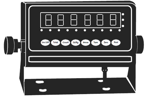
The display indicator utilizes an LED (Light Emitting Diode) display. LEDs are used indoors where brightness is needed. The tables below summarize the LED and key functions.
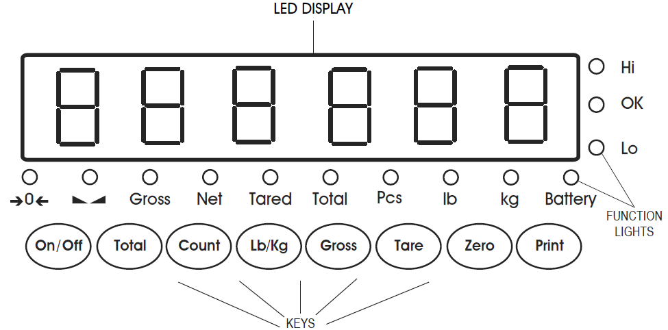
LED FUNCTIONS
| LED | INSTRUCTION |
| Weighing data | |
| kg | kg |
| lb | lb |
| Hold | Data hold |
| Gross | Gross weight |
| Net | Net weight |
| Tared | Tare |
| The weighing data is stable | |
| 0 | Weight is zero |
| Hi | Overload |
| OK | Ok |
| Lo | Underload |
| . | Decimal |
| Pcs | Show the counting status |
| Total | Go to accumulation mode |
KEY FUNCTIONS
| KEYS | KEY NAME | KEY FUNCTION |
| Power on/off | Press two seconds to power on or power off. | |
|
|
Accumulation | Accumulation.
Works with PRINT key to perform the accumulation function and check the accumulation result. |
| Counting | Counting operation. | |
| Lb/Kg Convert | Convert between lb and kg. | |
| Gross Weight | At Net Weight mode, check the gross weight. After three seconds, reverts back to net weight automatically. | |
| Tare | At Gross Weight mode, get the Tare Weight.
At Net Weight mode, clear the tare, get the Gross Weight. |
|
| Zero | Zeros the weight within tolerance. | |
| Works with ZERO, TARE, ON/OFF keys to perform functions. Print. |
OPERATION
POWER ON/OFF
- Press the ON/OFF key for two seconds to turn the scale on or off.
- When turning on, the indicator will show 000000-999999 before entering weighing mode.
- Check that the LED display and the status lights are working properly.
ZERO
INITIAL ZERO SETTINGWhen turning the scale on, if the weight on the display indicator is within the initial zero tolerance, the indicator will show 0.
MANUAL ZERO SETTING
- Wait for the scale to stabilize.
- Press the ZERO key. The display will show zero weight.
TARE
- Press the TARE key.
- The indicator will show the net weight. The Net and Tare function lights will light up.
- Press the TARE key. Zero the weight.
- The indicator will display the gross weight.
ACCUMULATION
- Zero the weight. Load weight until the scale stabilizes.
- Press the TOTAL key to enter accumulation mode.
- Total function light will light up. Display will read n 001 then will display the loaded weight.
- Unload the weight. Zero the weight. Load the second weight until the scale stabilizes.
- Press the TOTAL key. The display will read n002, then display the second loaded weight.
- Repeat a maximum of 999 times.
CHECK THE ACCUMULATION
- Press and hold the PRINT key. Press the TOTAL key.
- Display will read n**, then will show total weight.
NOTE: There are 8 digits total. The display shows the first 4 digits, then the last 4 digits.
For example, when the first 4 digits displayed are “0012” and the last 4 digits displayed are “34,56,” the weight is “1234.56.”
EXIT ACCUMULATION
- When the indicator shows the last four digits, press and hold the TOTAL key. The indicator will read clr n.
- Press the PRINT key to exit. If you want to clear the total weight, press the ZERO or TARE key. The indicator will read clr y.
- Press the PRINT key to clear the total weight and exit accumulating mode.
- If the weight is stable, connect the scale to the printer.
- Press the PRINT key.
NOTE: While in tare mode, print with tare. If the scale shows a negative weight, printing is not allowed.
COUNTING
Use this mode to count parts of uniform weight.
- In weighing mode, remove all weight from the platform.
- Press the COUNT key to enter the counting mode. PCS 0 will be shown on the display.
- Press the ZERO key to change the sample quantity – 5, 10, 20, 50, 100, 200 or 500 units.
- Place the sample quantity of the item being counted on the scale platform and press the PRINT key. Sample quantity will be shown on the display.
- Place remaining objects on the platform. The total quantity will be shown on the display.
- Press the COUNT key to return to weighing mode.
- To weigh different weights, at weighing mode put the item on the scale and press the COUNT key. The indicator will read 0.
- Press and hold the Count key. Press the ON/OFF key. The indicator will show PCS 0.
- Press the ZERO key and input the sample quantity.
- Press the PRINT key to enter. Repeat steps 2 and 3.
TROUBLESHOOTING
POSSIBLE TARE OPERATION CODES
| ERROR | REASON | SOLUTION |
| UUUUUUUU | Weight overload.
Bad connection with load cell. Load cell has quality problem. |
Reduce the weight.
Check load cell connection.
Inspect load cell. Check input and output. |
| nnnnnnn | Calibration error. Bad connection.
Load cell has quality problem. |
Check that scale is level. Check load cell connection.
Inspect load cell. Check input and output. |
MAINTENANCE
- Protect the display indicator from direct sunlight.
- Maintain a good connection between load cell and indicator.
- Keep indicator away from strong electric and magnetic fields.
- Power off the indicator during electrical storms.
- Power off the indicator before plugging and unplugging.
![]()
References
[xyz-ips snippet=”download-snippet”]