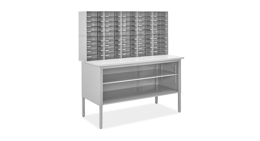
![]() MAILROOM TABLE / MAIL SORTER WORKSTATION1-800-295-5510uline.com
MAILROOM TABLE / MAIL SORTER WORKSTATION1-800-295-5510uline.com
TOOLS NEEDED
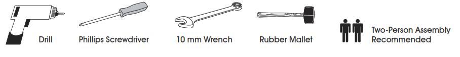
TABLE PARTS
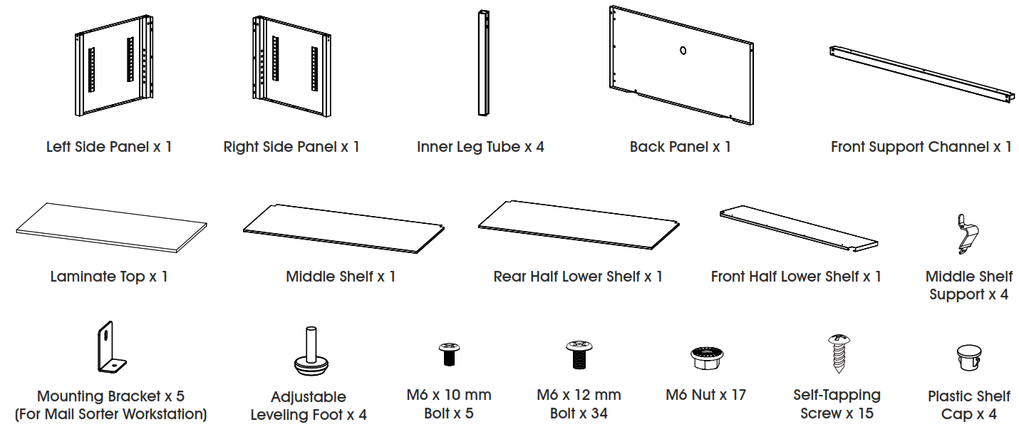
TABLE ASSEMBLY
 Table frame will need to be assembled first for all products. After the table frame is assembled, follow instructions for the next steps to assemble the purchased product.
TABLE FRAME ASSEMBLY
![]() NOTE: Count and inspect all pieces before disposing of any cartons or packing materials.
NOTE: Count and inspect all pieces before disposing of any cartons or packing materials.
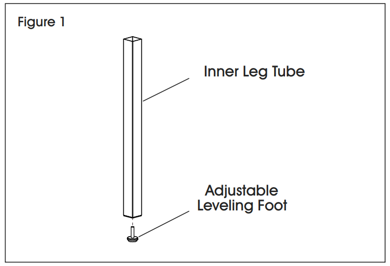
- Insert adjustable leveling feet into ends of inner leg tubes. (See Figure 1)

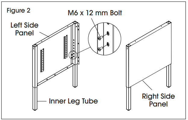
- Insert inner leg tubes into side panels and place them at the desired height. Using a Phillips screwdriver, attach the inner leg tube to side panels by inserting two M6 x 12 mm bolts into threaded holes. (See Figure 2)NOTE: Height is adjustable from 29-351⁄2″ in 11⁄2″ increments. Tabletop adds 1″ to overall height.
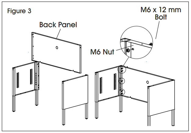
- Attach back panel to each side panel with six M6 x 12 mm bolts and six M6 nuts using a Phillips screwdriver. (See Figure 3)
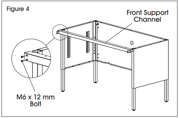
- Attach the front support channel to each side panel by inserting two M6 x 12 mm bolts into threaded holes. (See Figure 4)
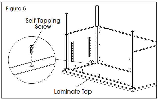
- Place laminate top upside down on a smooth, non-marring surface to prevent scratching. Pre-drilled holes in the laminate top should be facing up.
- Carefully flip the table frame over and place it on top of the laminate top. Carefully align the mounting holes in the table frame and pre-drilled holes in the laminate top. Using a drill, attachable frame to the laminate top with 10 self-tapping skews. (See Figure 5)
- Once the laminate top is attached, flip the table back over onto its feet.
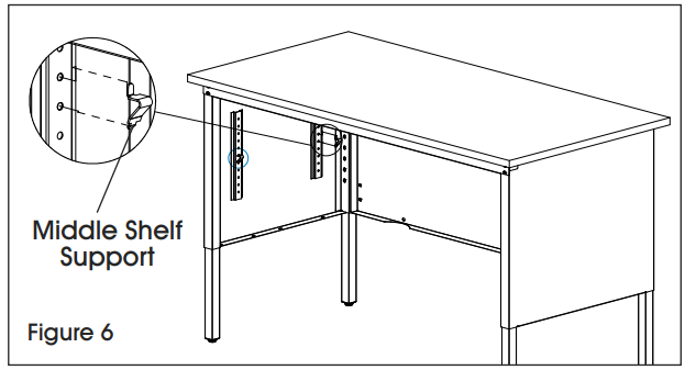
- Insert middle shelf supports at the desired height. (See Figure 6)}NOTE: Middle shelf is optional and can be attached at a later time.
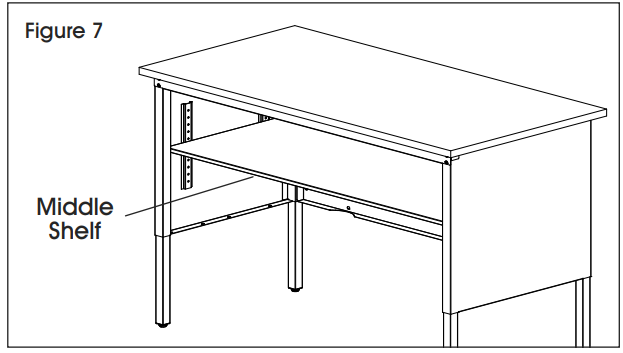
- Insert middle shelf with cut sections facing back corners of the table frame. The middle shelf will rest on top of the middle shelf supports. (See Figure 7)
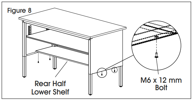
- Insert rear half lower shelf with cut sections facing back corners of the table frame. Attach the rear half lower shelf to side panels with four M6 x 12 mm bolts using a Phillips screwdriver. (See Figure 8)NOTE: Middle shelf may need to be raised to the highest setting to insert lower shelves.
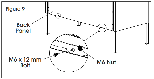
- Attach the rear half lower shelf to the back panel with two M6 x 12 mm bolts and two M6 nuts using a Phillips screwdriver. (See Figure 9)
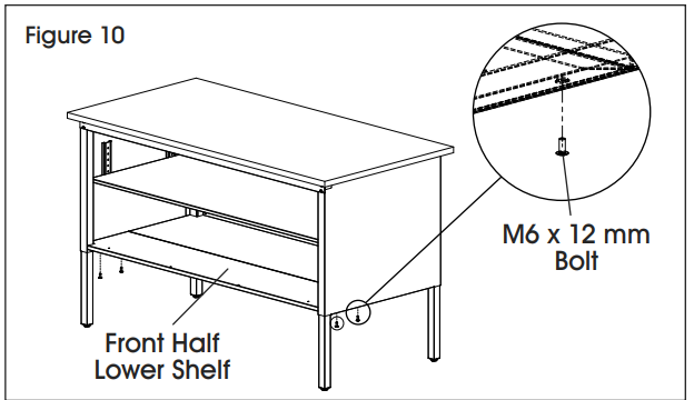
- Insert front half lower shelf with cut sections facing front corners of the table frame. Attach the front half lower shelf to side panels with four M6 x 12 mm bolts using a Phillips screwdriver. (See Figure 10) If sliding doors will not be installed, insert plastic shelf caps into holes in the front half lower shelf.
![]() NOTE: Front half lower shelf is optional and can be attached at a later time.
NOTE: Front half lower shelf is optional and can be attached at a later time.![]() NOTE: Knockout in the back panel can be removed using a flathead screwdriver and hammer.
NOTE: Knockout in the back panel can be removed using a flathead screwdriver and hammer.
STOP – IF YOU PURCHASED:
| ITEM # | DESCRIPTION | NEXT STEP |
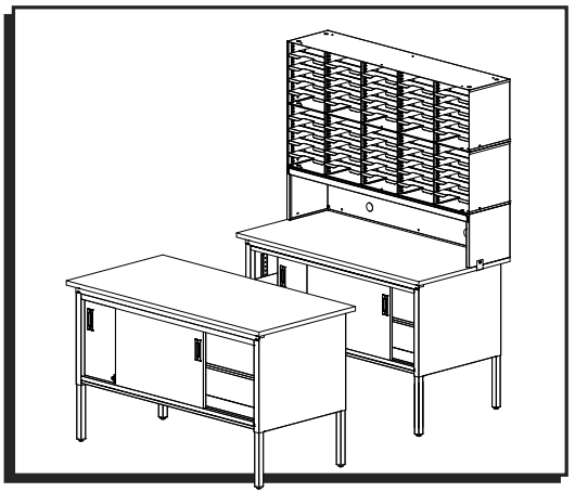
| H-8354 | 60 x 30″ Mailroom Table | Assembly Complete |
| H-8355 | 60 x 30″ Mailroom Table with Sliding Doors | Proceed to Sliding Door Assembly |
| H-8348 | Mail Sorter Workstation – 50 Slots | Proceed to Mail Sorter Workstation Assembly |
| H-8349 | Mail Sorter Workstation – 50 Slots with Riser | Proceed to Mail Sorter Workstation with Riser Assembly |
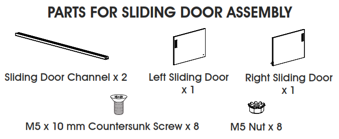
SLIDING DOOR ASSEMBLY
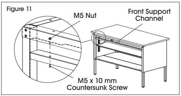
- Attach top sliding door channel to front support channel with four M5 x 10 mm countersunk screws and four M5 nuts using a Phillips screwdriver. (See Figure 11)
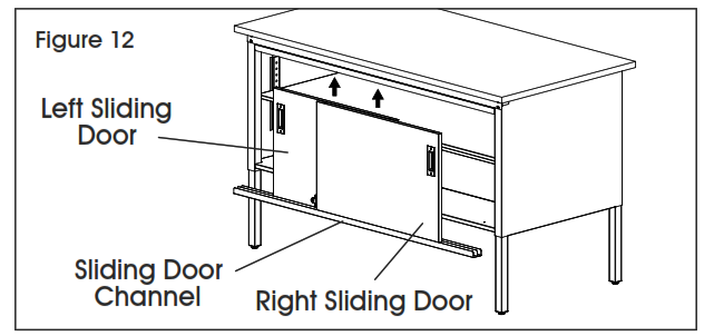
- Place left sliding door and right sliding door into bottom sliding door channel. The left door should be in the backchannel and the right door should be in the front channel. While lifting into place, place left door into backchannel and right door into the front channel of top sliding door channel. (See Figure 12)NOTE: The lock may need to be disengaged to slide doors together.
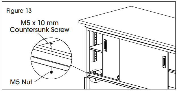
- Once doors are correctly positioned in both sliding door channels, attach the bottom sliding door channel to the front half lower shelf with four M5 x 10 mm countersunk screws and four M5 nuts using a Phillips screwdriver. (See Figure 13)
- Assembly is complete.
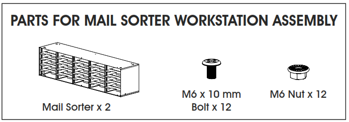
MAIL SORTER WORKSTATION ASSEMBLY
- Complete Table Frame Assembly starting on page 1.
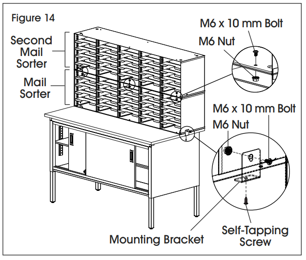
- Place one mail sorter on the rear of the laminate top.
- Attach five mounting brackets to mail sorter with five M6 x 10 mm bolts and M6 nuts. Fasten mounting brackets to the laminate top with five self-tapping screws using a drill. (See Figure 14)NOTE: Two mounting brackets will be attached to each side and three will be attached to the back.
- Stack second mail sorter on top of attached mail sorter. Fasten mail sorters together with six M6 x 10 mm screws and M6 nuts using a Phillips screwdriver. Holes are located in front and rear of sorters on far left, center, and far-right columns. (See Figure 14)NOTE: Mail sorter shelves may need to be removed to allow for space for the Phillips screwdriver to fully tighten screws and nuts.
- Assembly is complete.
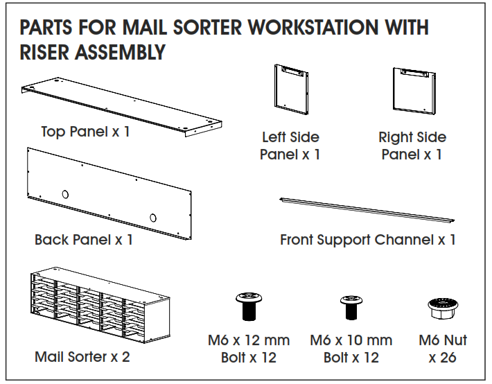
MAIL SORTER WORKSTATION WITH RISER ASSEMBLY
- Complete Table Frame Assembly starting on page 1.
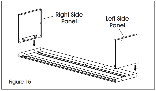
- Place the riser top panel upside down on a smooth, non-marring surface to prevent scratching.
- Attach the right-side panel by inserting locking tabs into matching square holes on the top panel. Gently tap with a rubber mallet to fully engage tabs. Repeat for the left side panel. (See Figure 15)NOTE: Locking tabs can be adjusted open or closed with a flathead screwdriver for easy assembly.
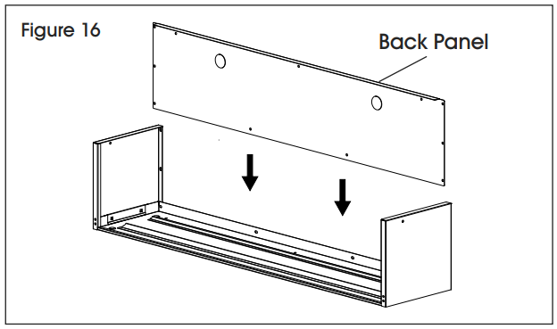
- Place back panel inside side panels and top panel. (See Figure 16)
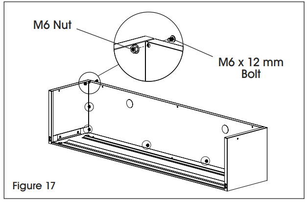
- Insert eight M6 x 12 mm bolts and M6 nuts and fasten back panel to side panels and top panel using a Phillips screwdriver. (See Figure 17)
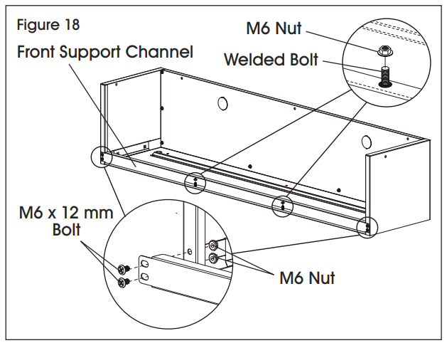
- Attach front support channel to side panels with four M6 x 12 mm bolts and M6 nuts using a Phillips screwdriver. Attach front support channel to top panel by fastening two M6 nuts to the welded bolts on the top panel. (See Figure 18)
- Place riser on the rear of laminate top.
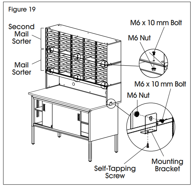
- Attach five mounting brackets to the base of the riser with five M6 x 10 mm bolts and M6 nuts. Fasten mounting brackets to the laminate top with five self-tapping screws using a drill. (See Figure 19)
- Stack one mail sorter on top of the riser. Fasten mail sorter to the riser with six M6 x 10 mm bolts and M6 nuts using a Phillips screwdriver. Holes are located in the front and rear of the sorter on the far left, center, and far-right columns. (See Figure 19)
- Stack second mail sorter on top of attached mail sorter. Fasten together with six M6 x 10 mm screws and M6 nuts using a Phillips screwdriver. (See Figure 19)NOTE: Mail sorter shelves may need to be removed to allow for space for the Phillips screwdriver to fully tighten screws and nuts.
- Assembly is complete.
![]() NOTE: Knockouts in the table and riser back panels can be removed using a flathead screwdriver and hammer.
NOTE: Knockouts in the table and riser back panels can be removed using a flathead screwdriver and hammer.
![]()
1-800-295-5510uline.com
[xyz-ips snippet=”download-snippet”]