![]()
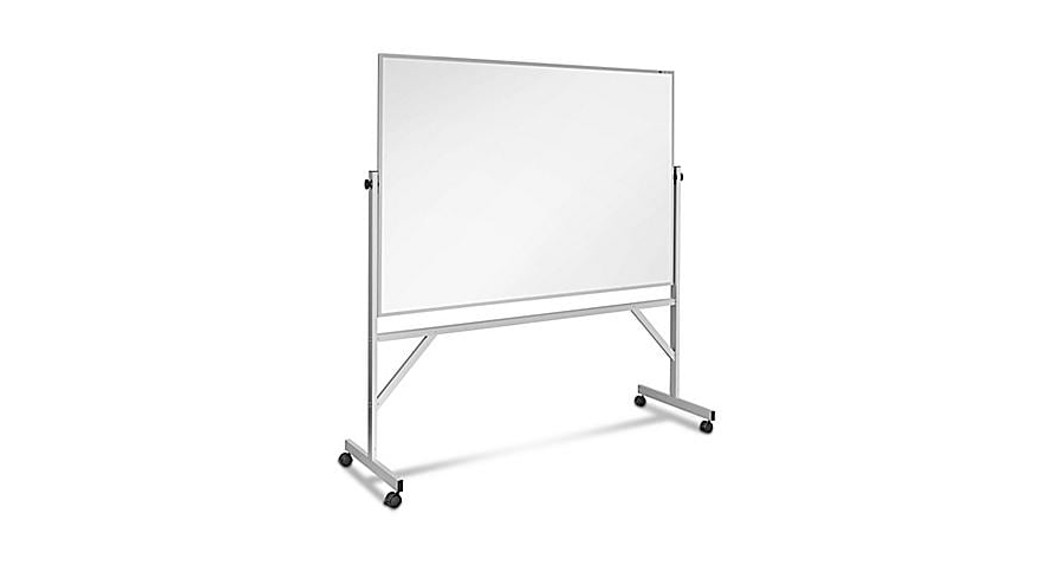
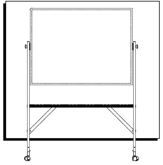
MOBILE DRY ERASE BOARD1-800-295-5510uline.com
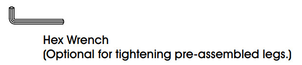
TOOLS NEEDED

TOOL INCLUDED
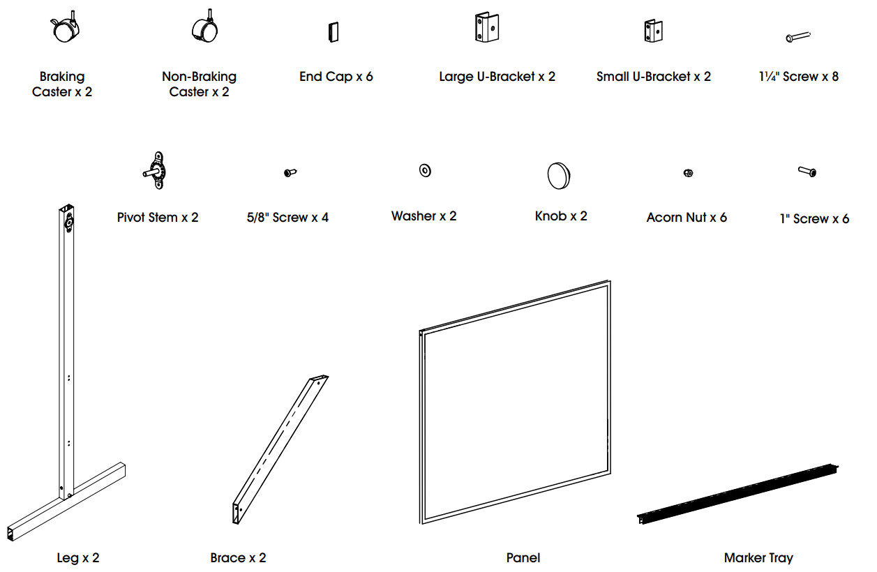
PARTS LIST
ASSEMBLY INSTRUCTIONS
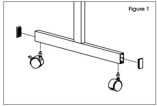
- Screw one braking and one non-braking caster into each foot. Fully tighten the nuts that accompany each caster. Insert one plastic end cap to the ends of each foot. (See Figure 1)

- Insert one plastic end cap to the top end of each leg.
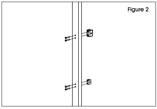
- Attach one small U-bracket to each leg at the lower set of holes using 1¼” screws. Attach one large U-bracket to each leg at the upper set of holes, using 1¼” screws. (See Figure 2) NOTE: Do not tighten screws until Step 9 is completed.
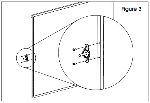
- Attach one pivot stem to both sides of the panel using two 5/8″ screws for each pivot stem. Fully tighten screws. (See Figure 3)
- Lay the leg and feet assemblies on a table. Position the legs so that the U-brackets face each other.
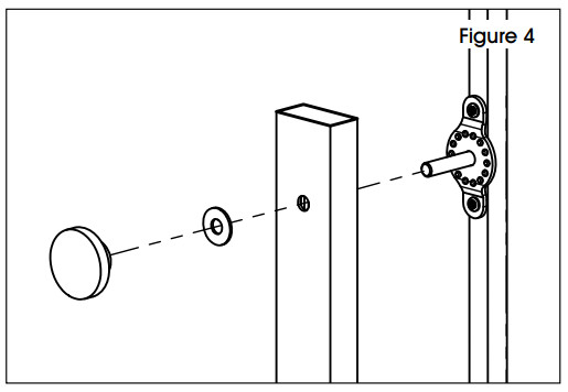
- Place the panel between the legs, and insert the pivot stems through the top hole in each leg. Place a washer and knob on each stem. (See Figure 4) NOTE: Do not fully tighten the knobs.
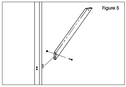
- Attach one brace to each leg using one 1″ screw and one acorn nut. The brace slides over the small U-bracket. Repeat for the other leg. (See Figure 5)
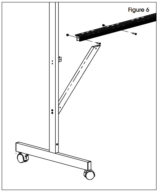
- Attach the marker tray to the leg assemblies by setting the marker tray on top of the large U-brackets and the braces. Align the holes and install one 1″ screw and one acorn nut through each of the four holes. (See Figure 6)
- Place the unit upright and insert an end cap in the top of each leg. Tighten all screws and nuts to complete the assembly.
![]()
MOBILE DRY ERASE BOARD1-800-295-5510uline.com
[xyz-ips snippet=”download-snippet”]