ULINE Pneumatic Roll Stapler Instructions
STAPLER SPECIFICATIONS
Dimensions (L x H x W): 9 x 9 x 4.5″Weight (without fasteners): 5.5 lbs.Compressed Air:Maximum PSI: 110 psiRecommendedOperating Pressure: 70–100 psiAir Consumption: 2.4 CFMStaple Specification: S-860 RR1-58 RollStaple Specification: S-861 RR1-34 RollStaple Capacity: 1,000 staplesNoise Levels: 89 dBA
WARNING
Before operating this stapler familiarize yourself with the safety warnings and instructions in this manual. Keep these instructions with the stapler for futurereference. If you have any questions, contact Uline at 1-800-295-5510.
SAFETY INSTRUCTIONS
- Read the manual and understand all safety instructions before operating the tool. If you have questions, contact Uline at 1-800-295-5510.
- Never use flammable gases as a power source for the stapler. Only use filtered, compressed air.
- Never use gasoline or other flammable liquids to clean the stapler. Vapors left on the stapler could ignite and cause the tool to explode.4.
- Do not exceed 110psi of air pressure when operating the stapler.
- Disconnect the stapler from the air supply before making adjustments, cleaning or clearing jams and when not in use.
- Do not pull the trigger when carrying or holding the stapler.
- Never carry the stapler by the hose or pull on the hose to move the stapler.
- Always wear protective equipment; i.e. safety glasses, hearing protection and head protection.
- Do not use a check valve or any other fitting which allows air to remain in the stapler.
- Do not place your hand or any other body part in the staple clinching area or adjustment window when connecting or disconnecting the air supply.
- Never point the stapler at yourself or anyone else.
LUBRICATION & MAINTENANCE
- Lubricate the stapler prior to initial operation.
- Disconnect the stapler from the air supply prior to servicing.
- Turn the stapler so that the inlet is facing up and put one drop of high-speed spindle oil, UNOCOL RX22, or 3-in-1 oil into air inlet. Never use detergent oil or additives.
- Operate the tool briefly after adding oil.
- Wipe off excessive oil at the exhaust. Excessive oil will damage the O-rings. If inline oiler is used, manual lubrication through the air inlet is not required on a daily basis.
AIR SUPPLY AND CONNECTIONS
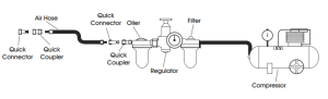
NOTE: The following illustration shows the correct mode of connection to the air supply system which will increase the efficiency and life of the stapler.Many air tool users find it convenient to use an inline oiler to provide oil circulation through their tool. Check oil level in the oiler daily.A filter is recommended on your air compressor. Check the filter and drain on a daily basis.
SAFETY INSTRUCTIONS CONTINUED
LOADING THE STAPLER
- Disconnect the air supply.
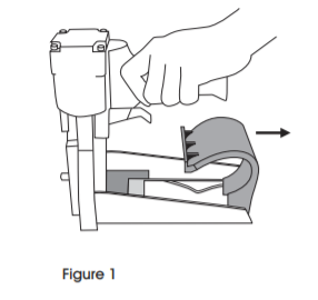
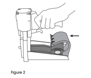
- Slightly squeeze the cover back, then pull the top cover open. (See Figure 1)
- Place coil staples in magazine. Feed front end of coil staples into right coil guide, left coil guide and top guide. Push forward until stopping in driver guide unit. (See Figure
- Swing cover closed and squeeze to snap closed. Check position engagement. (See Figure 2)
STAPLE LEG LENGTH
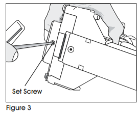
- Loosen the set screw on the bottom with a 3mm Allen wrench. (See Figure 3)
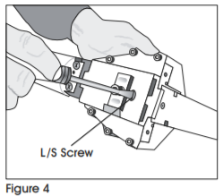
- Adjust L/S screw with a screwdriver to the desired setting. (See Figure 4)a. If you are using 3/4″ staples set L up.b. If you are using 5/8″ staples set S up. (See Figure 5)
- Tighten the set screw on the bottom.
 a. If you are using 3/4″ staples set L up.b. If you are using 5/8″ staples set S up. (See Figure 5)
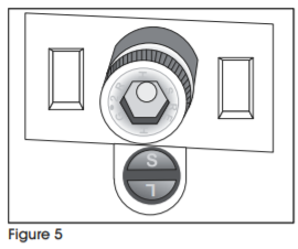
SAFETY INSTRUCTIONS CONTINUED
CLINCH ADJUSTMENT
Use 2.5mm Allen wrench and turn collar through window clockwise to tighten clinch. (See Figure 6)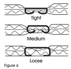
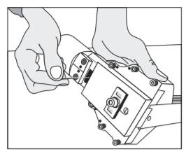
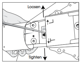
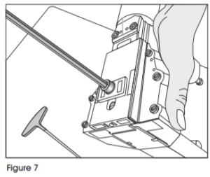
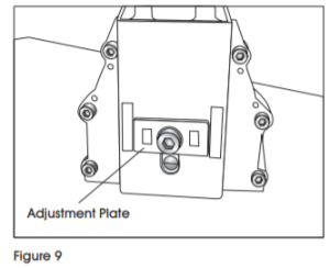
DEPTH ADJUSTMENT
- Loosen front screw with a 6mm Allen wrench. (See Figure 7)
- Push the body up and adjust to the desired depth. (See Figure 8)
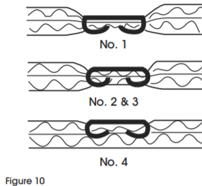
- When the top edge of the adjustment plate is at its highest setting, the teeth are at their shallowest penetration. (See Figure 9)
- If set at No. 1 the teeth are at their deepest penetration. (See Figure 10)

OPERATING INSTRUCTIONS
- Protect your eyes and ears.a. Wear safety glasses with side shieldsb. Wear hearing protection.c. Ensure that anyone in the vicinity wears safety protection.
- To prevent accidental injuries, never place a hand or any other body part in the staple clinching area or adjustment window.
- Never point the stapler towards you or anyone else.
- Always handle the stapler with care. Never pull the trigger unless tool is ready for operation.
- Check and replace any damaged or worn components on the stapler.
- Add a few drops of oil into the air inlet.
- Install a quick connect fitting to the stapler.
- Regulate the air pressure to attain 70–100 psi.
- Insert the staples into the tool following the loading instructions.
- Reconnect the air hose to the stapler.
- Grasp the handle with one hand on box in line with the desired staple location. There is a small projection on either side of the magazine seat as an aid in locating the position of the staple.
- The strongest closure requires staples close to the ends of the box.
WARNING
Never use gasoline or other flammable liquids to clean the stapler. Vapors in the stapler could be ignited by a spark and cause the stapler to explode.
CLEANING THE STAPLER
- Disconnect the air supply from the stapler.
- Remove tar buildup with non-corrosive cleaner.CAUTION! Do not allow solvent to get into the cylinder or damage may occur.
- Dry the stapler completely before use.
OPERATING INSTRUCTIONS CONTINUED
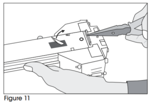
- Disconnect air supply.
- Pull up lever. (See FIgure 11)
- Insert needle nose pliers or screw driver to clear jam. (See Figure 11)
- Push down lever.
WARNING
Stop using the stapler immediately if any of the following problems occur. Serious personal injury could occur. Any repairs or replacements must be done by a qualified person or authorized service center only.
TROUBLESHOOTING
| PROBLEM | CAUSE | REMEDY |
| Air leak from trigger | O-ring on valve or on tube is damaged. | Replace O-ring. |
| Air leak from exhaust port | O-Ring on valve or on tube is damaged.
O-Ring on piston is damaged. |
Replace O-ring. |
| Air leak from cylinder | Piston rod port O-ring is damaged. | Replace O-ring. |
| Slow & short travel cycling | Check for loose screw or wear of parts. | 1. Position eccentric pin and tighten screw.
2. Recheck for maximum efficiency. a. Adjust pin slightly upward if due to short travel. b. Adjust pin slightly downward if due to slow cycling. |
| Excessive jams | 1. Slow & short travel cycle.
2. Teeth screws are loose. 3. Wrong staple size. 4. Insufficient lubrication. |
1. Adjust as noted above.
2. Tighten screws. 3. Check staples. 4. Clean and lubricate. |
| Uneven clinch | Wrong staple size. | Check for proper leg length adjustment and clincher size. |
| Unclinched staple | 1. Teeth are loose or broken.
2. Slow & short travel cycle. |
1. Check & replace teeth as needed.
2. Adjust as noted above. |
OPERATING INSTRUCTIONS CONTINUED
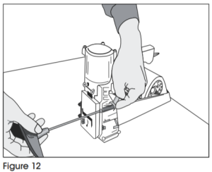
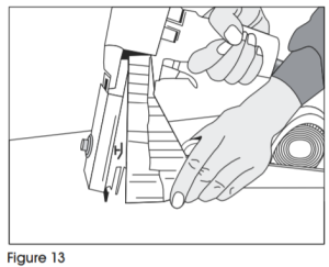
TEETH REPLACEMENT
- Loosen screws and nut with an 8mm wrench and 4mm Allen wrench. (See Figure 12)
- Remove the magazine assembly. (See Figure 13)
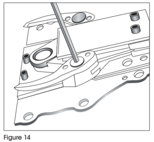
- Loosen screws with 3mm Allen wrench. (See Figure 14)
- Change teeth one at a time to prevent reverse teeth.
OPERATING INSTRUCTIONS CONTINUED
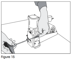
DRIVER REPLACEMENT
- Disconnect the air supply.
- Loosen screw and nut with a 8mm spanner wrench and a 4mm Allen wrench. (See Figure 15)
- Remove the magazine assembly. (See Figure 16)
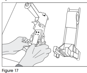
- Loosen the set screw with a 3mm Allen wrench to unlock the adjusting rod.
- Slide the linkage mechanism and adjusting rod simultaneously from the collar. (See Figure 17)
- Loosen the screws with a 3mm Allen wrench. (See Figure 18)
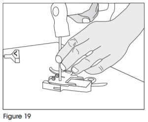
- Take off the spring pin with a hammer and 6mm straight rod. (See Figure 19)


OPERATING INSTRUCTIONS CONTINUED
VALVE AND TUBE O-RING REPLACEMENT
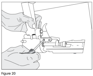
- Loosen screws with a flat screw driver. (See Figure 20)
- Remove spring with needle-nose pliers. (See Figure 21)
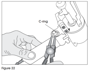
- Remove C-ring with C-ring pliers. (See Figure 22)
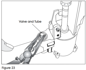
- Remove valve and tube with needle-nose pliers. (See Figure 23)

OPERATING INSTRUCTIONS CONTINUED
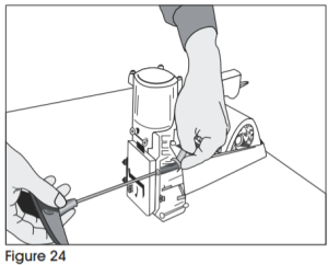
PISTON REPLACEMENT
- Remove screws and nut with 8mm Spanner wrench and 4 mm Allen wrench. (See Figure 24)
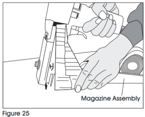
- Remove magazine assembly. (See Figure 25)
- Loosen set screw with a 3mm Allen wrench to unlock the adjusting rod.
- Slide linkage mechanism and adjusting rod simultaneously from collar.
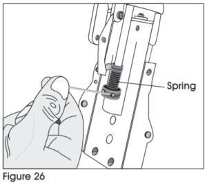
- Loosen collar with a 3mm straight rod to remove the spring. (See Figure 26)
- Loosen screw with a 3mm Allen wrench and remove the block through the window.
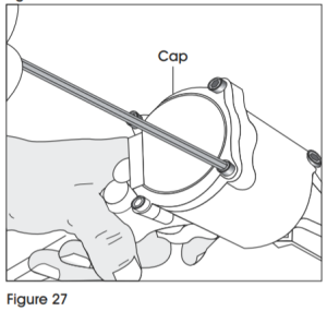
- Loosen screws with a 3mm Allen wrench and remove the cap. (See Figure 27)
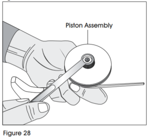
- Remove the piston assembly with a 10mm Spanner wrench. (See FIgure 28)
- Remove piston and replace.
Read More About This Manual & Download PDF:
References
[xyz-ips snippet=”download-snippet”]