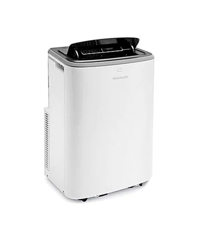
ULINE Portable Air Conditioner H-5274 Installation Guide
ACCESSORIES INCLUDED
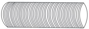
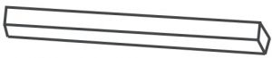
- Exhaust Hose x 1

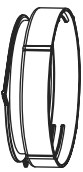
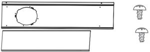
- Unit/Exhaust Adapter A x 1
- Window/Exhaust Adapter B x 1
- Foam Seal x 3
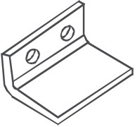
- Window Slider Kit x 1
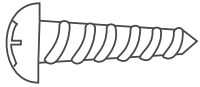
- 1/2″ Screw x 4
- 3/4″ Screw x 2
- 1/2″ Hex Head Cap Screw x 2
- Remote Control x 1
- Sash Lock x 1
- Battery (For Remote Control) x 2


SAFETY
![]() WARNING! Read this section before attempting to operate air conditioner. Unit must be upright one hour prior to operating.
WARNING! Read this section before attempting to operate air conditioner. Unit must be upright one hour prior to operating.
The power supply cord contains a current device that senses damage to the cord. To test your power cord, do the following:
- Plug in the air conditioner.
- The cord will have two buttons on the plug head. Press the TEST button. You will notice a click as the RESET button pops out.
- Press the RESET button. Again, you will notice a click as the button engages. (See Figure 1)
- The power cord is now supplying electricity to the unit.

![]() NOTE: Do not use this device to turn the unit on or off. Always make sure the RESET button is pushed in for correct operation. The power cord must be replaced if it fails to reset when either the TEST button is pushed or if it cannot be reset. If power supply cord is damaged, it cannot be repaired. It must be replaced.Contact Uline Customer Service for assistance at 1-800-295-5510.
NOTE: Do not use this device to turn the unit on or off. Always make sure the RESET button is pushed in for correct operation. The power cord must be replaced if it fails to reset when either the TEST button is pushed or if it cannot be reset. If power supply cord is damaged, it cannot be repaired. It must be replaced.Contact Uline Customer Service for assistance at 1-800-295-5510.
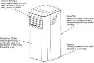
NORMAL SOUNDS
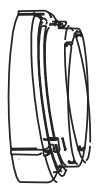
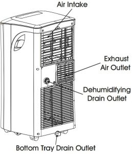
UNIT DESCRIPTION

INSTALLATION
EXHAUSTING HOT AIR
In cooling mode, the appliance must be placed close to a window or opening so that the warm exhaust air can be ducted outside.
First, position unit on a flat floor. Make sure there is a minimum of 12″ clearance around the unit and that it is within the vicinity of a single circuit outlet power source.
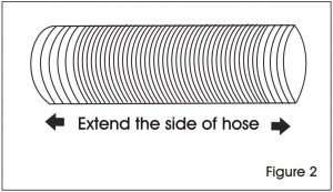
- Extend either side of the hose. (See Figure 2)
- Screw the hose onto adapter A. (See Figure 3)
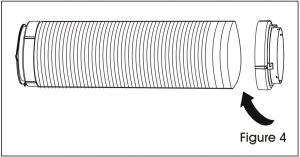
- Extend the other side of the hose and screw it to adapter B. (See Figure 4)
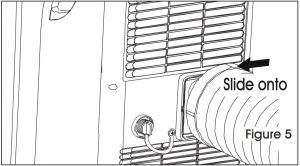
- Slide the assembly onto unit. (See Figure 5)
- Affix adapter B into the window slider kit and seal. (See Figures 6 and 7)The hose can be extended from its original length of 15″ up to 59″, but it is the best to keep the length to the minimum required. Also, make sure that the hose does not have any sharp bends or sags. (See Figure 8)

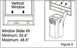
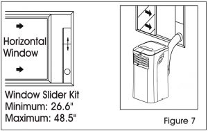 The hose can be extended from its original length of 15″ up to 59″, but it is the best to keep the length to the minimum required. Also, make sure that the hose does not have any sharp bends or sags. (See Figure 8)
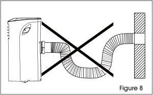
INSTALLATION IN A DOUBLE HUNG SASH WINDOW
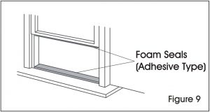
- Cut the adhesive-type foam seals to the proper lengths and attach them to the window and sill. (See Figure 9)
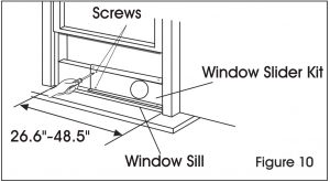
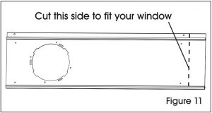
- Open the lower sash and place the window slider kit on the window sill. (See Figure 10) Adjust the length of the window slider kit according to the width of window. Screw down the two screws on the window slider kit. (See Figure 10) Cut the adjustable window slider kit if the width of window is less than 26.6″. (See Figure 11)
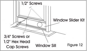
- Close the lower sash securely against the window slider kit. (See Figure 12)
- Drive two 1/2″ screws to secure the window slider kit to the lower sash. (See Figure 12)
- Secure the window slider kit to the window sill. (See Figure 12)
- For wooden windows, use 3/4″ screws for securing.
- For Vinyl-Clad windows, use 1/2″ hex head cap screws for securing.
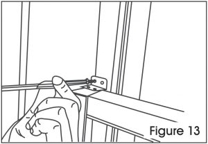
- To secure lower sash in place, attach sash lock with 1/2″ screw as shown. (See Figure 13) NOTE: It is difficult to lock vinyl-clad windows with the sash lock, so lock by window itself.
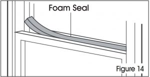
- Cut the foam seal to an appropriate length and seal the open gap between the top window sash andouter window sash, as shown. (See Figure 14)
INSTALLATION IN A SLIDING SASH WINDOW
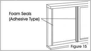
- Cut the adhesive type foam seals to the proper lengths and attach them to the window frame. (See Figure 15)
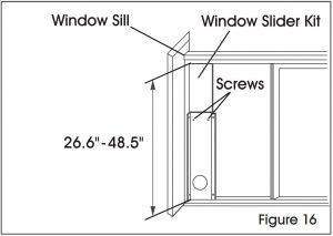
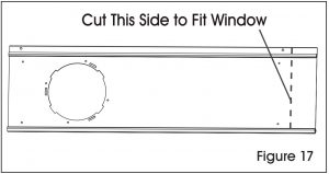
- Open the window sash and place the window slider kit on the window sill. (See Figure 16) Attach the window slider kit to the window sill. Adjust the length of the window slider kit according to the height of the window. Screw down the two screws on the window slider kit. (See Figure 16) Cut the adjustable window slider kit if the height of the window is less than 26.6″. (See Figure 17)
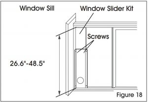
- Close the sliding sash securely against the window slider kit. (See Figure 18)
- Secure the window slider kit to the window sill. (See Figure 18)
- For wooden windows, use 3/4″ screws for securing.
- For Vinyl-Clad windows, use 1/2″ hex head cap screws for securing.
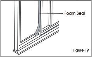
- Cut the foam seal to an appropriate length and seal the open gap between the sliding sash and outer window sash. (See Figure 19)
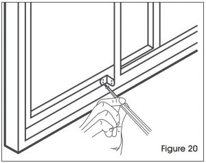
- To secure the sliding sash in place, attach sash lock with 1/2″ screw. (See Figure 20)
AIR CONDITIONER FEATURES
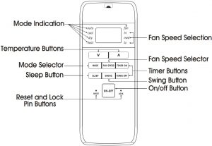
CONTROL PANEL

REMOTE CONTROL
- Battery Size: AAA
![]() WARNING! Do not mix old and new batteries. Do not mix alkaline, standard (carbon-zinc) or rechargeable (nickel-cadmium) batteries. This device complies with Part 15 of the FCC Rules. Operation is subject to the following two conditions: This device may not cause harmful interference. This device must accept any interference received, including interference that may cause undesired operation.
WARNING! Do not mix old and new batteries. Do not mix alkaline, standard (carbon-zinc) or rechargeable (nickel-cadmium) batteries. This device complies with Part 15 of the FCC Rules. Operation is subject to the following two conditions: This device may not cause harmful interference. This device must accept any interference received, including interference that may cause undesired operation.
![]() NOTE: The RESET button is depressed when you want to return to the initial factory settings. The LOCK button is depressed to lock the keypad so the settings cannot be changed. The key symbol will appear in the display of the remote control. Depress the LOCK button again to release. Use a small pin to depress these buttons.
NOTE: The RESET button is depressed when you want to return to the initial factory settings. The LOCK button is depressed to lock the keypad so the settings cannot be changed. The key symbol will appear in the display of the remote control. Depress the LOCK button again to release. Use a small pin to depress these buttons.
OPERATION
![]() NOTE: The following instructions explain the control panel, and they can be used for the remote control also.
NOTE: The following instructions explain the control panel, and they can be used for the remote control also.
COOLING MODE
In this mode, the exhaust adapter hose must be used:
- Press the MODE button until the “cool” indicator lights up.
- Press the “ ” temperature buttons for desired settings.
- Press the FAN SPEED button for desired fan speed.
DRY MODE
In this mode, you do not need to use the exhaust adapter hose, but the water collected must be discharged. See Drainage section on page 8.
- Press the MODE button until the “dry” indicator lights up.
- The fan will run at low speed and the display will show the room temperature.
- Keep doors and windows closed for best effect.
AUTO MODE
Always have the exhaust hose attached in this mode.When you set the air conditioner to auto mode, it will automatically select cooling or fan only operation depending on what temperature you have selected and the room temperature. The air conditioner will control room temperature automatically based on temperature set. Under auto mode, you cannot select the fan speed.
FAN MODE
In this mode, there is no need to use the exhaust hose or drainage hose. However, to remove stale or smokey air from the room, hook up the duct accessories as described in the Exhausting Hot Air section on page 3.
- Press the MODE button until the “fan” indicator lights up.
- Press the FAN SPEED button to choose the desired fan speed.
- The fan will run at the selected speed and the display will show the room temperature.
TIMER OPERATION
You can set both delay stop and delay start while unit is in ON or OFF position. When unit is in ON position, first press TIMER button to go to delay stop setting, then “timer off” light will illuminate. Tap or hold the UP arrow (∧) or the DOWN arrow (∨) to change delay stop timer at 0.5 hour increments up to 10 hours, then at 1 hour increments up to 24 hours. Then, press the TIMER button to confirm the setting (the control will confirm the setting automatically after 5 seconds) and go to delay start setting. Use the same way as above to set the delay start timing. If you do not need to set delay start, press the TIMER button again to exit. After 5 seconds, the control will automatically change the display backto previous temperature display. To check remaining time, press the TIMER button. The delay start operation automatically selects mode, temperature and fan speed the same as last operation set.
When unit is in OFF position, press TIMER button to first go to delay start setting, then “timer on” light will illuminate. Set the delay start and delay stop timing the same way as above.
To cancel the timer setting, simply tap the (∧) or (∨) button to change the timing to 0.0.
SLEEP OPERATION
In this mode, the selected temperature will increase by 2°F 30 minutes after the mode is selected. The temperature will then increase by another 2°F after an additional 30 minutes. This new temperature will be maintained for 7 hours before it returns to the originally selected temperature. This ends the Sleep mode and the unit will continue to operate as originally programmed. The sleep mode program can be cancelled at any time during operation by again pressing the SLEEP button.
![]() NOTE: This feature is unavailable under fan or dry modes.
NOTE: This feature is unavailable under fan or dry modes.
CHECK FILTER FEATURE
This feature is a reminder to clean the air filter (See Care and Cleaning) for more efficient operation. The light above the FILTER RESET button will illuminate after 250 hours of operation. To reset after cleaning the filter, press the FILTER RESET button and the light will go off.
FAULT CODE
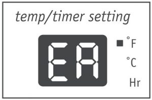
- If the display reads “EA,” the room temperature sensor has failed. Contact Uline Customer Service at 1-800-295-5510.
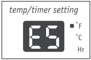
- If the display reads “ES,” the evaporator temperature sensor has failed. Contact Uline Customer Service at 1-800-295-5510.
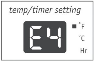
- If the display reads “E4,” the display panel communication has failed. Contact Uline Customer Service at 1-800-295-5510.
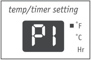
- If the display reads “P1,” bottom tray is full. Carefully move the unit to a drain location, remove the bottom drain plug and let the water drain away. Restart the machine until the “P1” symbol disappears. If error repeats, call Uline Customer Service at 1-800-295-55100.
DRAINAGE
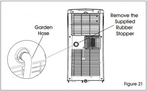
During the dehumidifying mode, you will need a garden hose (sold separately) to drain the condensate from the unit. Remove the rubber stopper from the hose connector. (See Figure 21)
The hose may then:
- Discharge into a drain that is lower than the unit.
- Be connected to a condensate pump (sold separately)
ADDITIONAL INFORMATION
- The “cool” circuit has an automatic three minute time-delayed start if the unit is turned off and on quickly. This prevents overheating of the compressor and possible circuit breaker tripping. The fan will continue to run during this time.
- The control will maintain the set temperature within 2°F, between 62°F and 86°F (17°C and 30°C)
- The control panel is capable of displaying temperature in Fahrenheit or Celsius. To convert from one to the other and back, press and hold the “Temp” Up (∧ ) and Down (∨ ) buttons together for three seconds.
- There is a two second delay for the compressor shutting down when selecting fan only. This covers the possibility of rolling through to another mode.
- After a power outage, the unit will memorize the last setting and return the unit to the same setting once power is restored.
CARE AND CLEANING
Clean your air conditioner occasionally to keep it looking new. Be sure to unplug the unit before cleaning to prevent shock or fire hazards.
AIR FILTER CLEANING
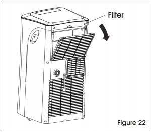
- This unit has one filter. Grasp the upper panel tab and take off the filter behind the grill of the back panel. (See Figure 22)
- Wash the filter using liquid dishwashing detergent and warm water. Rinse filter thoroughly. Gently shake excess water from the filter. Be sure filter is thoroughly dry before replacing.
- Instead of washing, you may vacuum the filter clean.
CABINET CLEANING
- The cabinet and front may be dusted with an oil-free cloth or washed with a cloth dampened in a solution of warm water and mild liquid detergent. Rinse thoroughly and wipe dry.
- Never use harsh cleaners, wax or polish on the cabinet front.
- Be sure to wring excess water from the cloth before wiping around the controls. Excess water in or around the controls may damagethe air conditioner.
WINTER STORAGE
If you plan to store the appliance during the winter, cover it with plastic or return it to its carton.
TROUBLESHOOTING
| OPERATING ISSUE | CAUSES | RECOMMENDATIONS |
| Air conditioner wit not operate. | Wall plug disconnected.Plug current device tripped.House Nse blown or circuit breaker tripped.Control is oft.Pt appears in the display window. | Push plug firmly into wall outlet. Press the RESET button.Replace fuse with lIme-delay type or reset circuit decker.Turn Control on and set to desired selling.Drain water as descnbed in Drainage section on Page 8.When the ar outlet exceeds 158′ F (70′ C). the automatic heat protection engages. Remove any blockages and let appliance cool down.Reset the temperature.Reset the temperature. |
| Shut ott in Heot mode. | ||
| Room Temperature lower than the set temperature (Cool Mode). | ||
| Room Temperature higher than the set temperatue (Heat Mode). | ||
| Alf ROM Witt does MX feel cold enough. | Cooling may not occur until room temperature rises above 601 (16t).Walt approximately three minutes ond listen tor compressor to restart when set in cod mode. | |
| Roan temperature below 601 (16-C). Reset to a lower temperature.Compressor shut on by changing modes. | ||
| Alr conditioner cooling. but room is too warm – ice forming on Ceding C011 beNnd front | Outdoor temperature below 601 (164CIAlt filter may be dirty.Temperaltre Is set too low tor nighttime coding. Exhaust duct not connected or blocked. | Coding may not occur until room temperature rises above 601 (1M).Clean 11110f. Peter to Core and Cleaning sedlon on pogo 9. To CletIOO, set to ton only mode. |
| To defrost the coil, set to tan oNy mode. Then. set temperature to a higher tiding.See Exhausting Hot Alr section on pope 3. | ||
| Alr conditioner cooling | Dirty or filter – air restricted. Temperatue is set too high. Alf directional louvers positioned improperly.Front of urn Is blocked by drcpes. blinds or furniture. which restrict dr distribution.Doors. windows or registers open and cold air escapes.Unit recently turned an in hot room. | Clean or triter. Peter to Care and Cleaning section on page 9.Sel temperature to a lower setting. POS.1110O louvers for better at distribution. Clear blockage In front at unit.Close doors, windows ix registers.Allow additional time to remove stored heat from walls. Cedrig. floor and kennure. |
| but room 15100 warn – no Ice forming on cooling coil behind front | ||
| AR conditioner turns on and oft rapidly. | Dirty or filter – all restricted. Oise° temperature extremely hot. | Clean at tiller.Set tan speed to desert selling to bring dr through |
| cooling coils more frequently. | ||
| Nose when unit is tooling. | At movement sound. Medan from uneven 11001. | This is normal. If too loud, set to lower Ion setting. MORO Of SUN:00d 0130113OCe CaTedly On Chen SUf10013. |
| ROOM :00 cold. | Set temperatue too low. | Increase set temperatue. |
| Room too h01. | Set temperatue too high. | Lower set temperature. |
Contact Us
Phone: 1-800-295-5510Web: uline.com
[xyz-ips snippet=”download-snippet”]