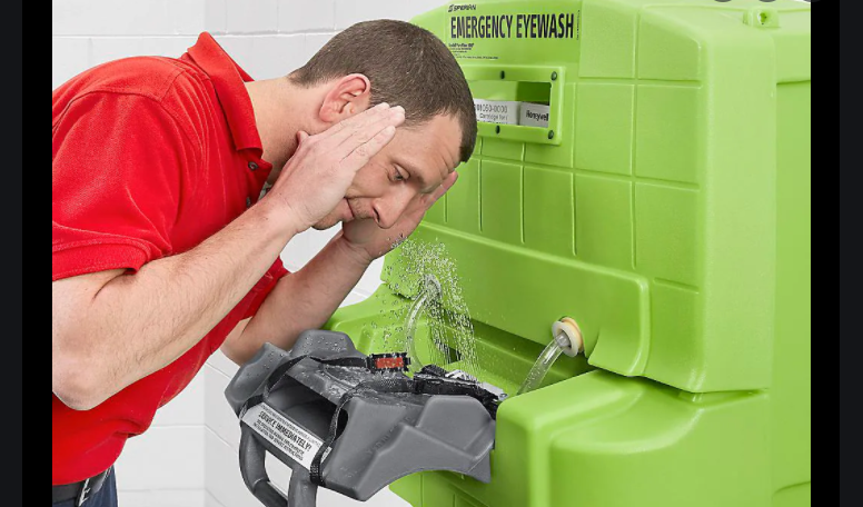
ULINE Pure Flow 1000 Eyewash Station

GENERAL INFORMATION
The H-1297 shipping carton should contain:
- Eye Wash Station
- Emergency Sign
- Hanging Bracket
Before installing S-11507 Pure Flow 1000® Saline Cartridges, inspect product for damage.NOTE: S-11507 Pure Flow 1000® Saline Cartridges are sold separately.
CARTRIDGE INSTALLATION
NOTE: This eyewash station requires two saline cartridges to be installed at the same time.
- Close the drain spigot by turning handle to the rear. (See Figure 1)
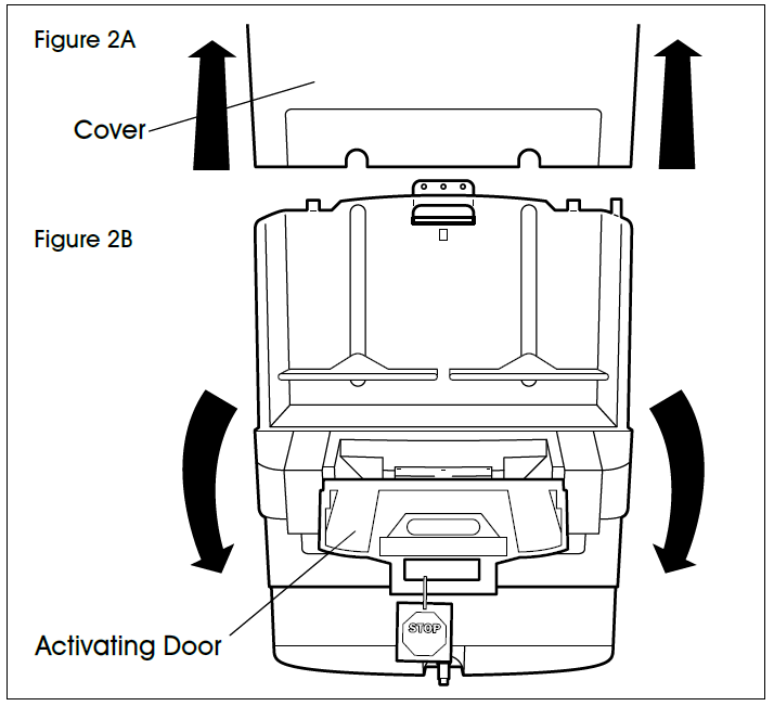
- Remove cover by lifting up. (See Figure 2A) Open activating door. (See Figure 2B)
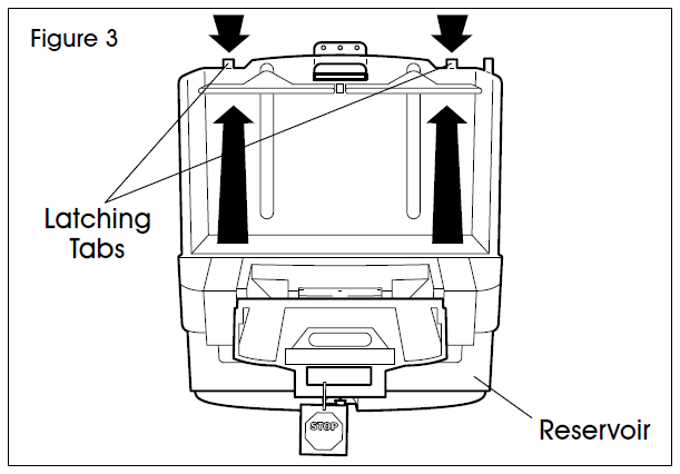
- Raise reservoir to “Up” position, latch on housing by pressing back on latching tabs. (See Figure 3)
- Place two S-11507 Pure Flow 1000® Saline Cartridges on the shelf. Nozzle assembly must be in front. (See Figure 4)
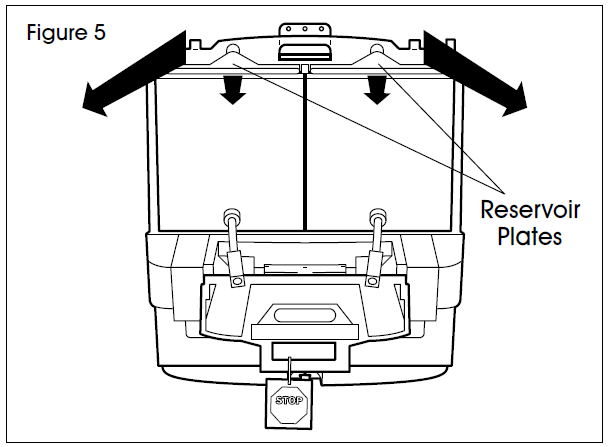
- Pull green latch tabs forward to drop down reservoir, ensuring that plates are seated on bags and are not resting on the cartridge boxes. (See Figure 5)
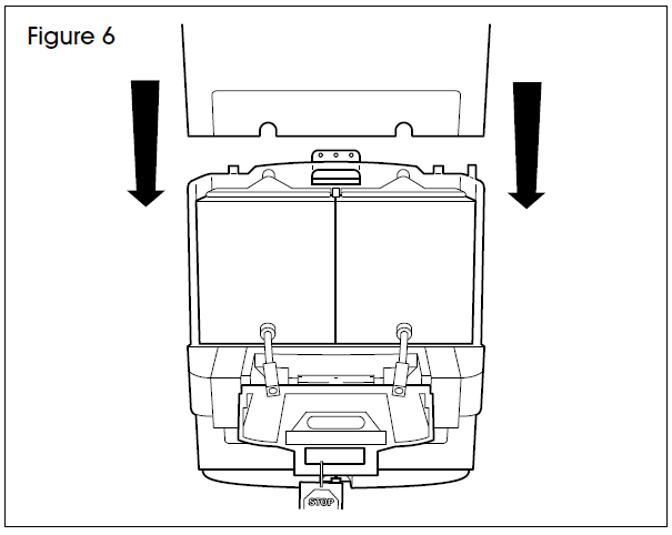
- Replace cover. (See Figure 6)
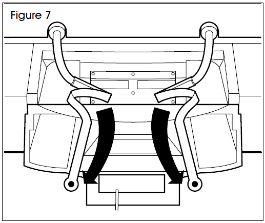
- Remove rubber bands from activating strap and nozzle. Extend activating straps to the side. Do not pull on the straps. (See Figure 7)
- Snap right-hand nozzle into place on white nozzle plate. An audible ‘click’ will be heard to confirm that the nozzle is engaged. (See Figure 8)
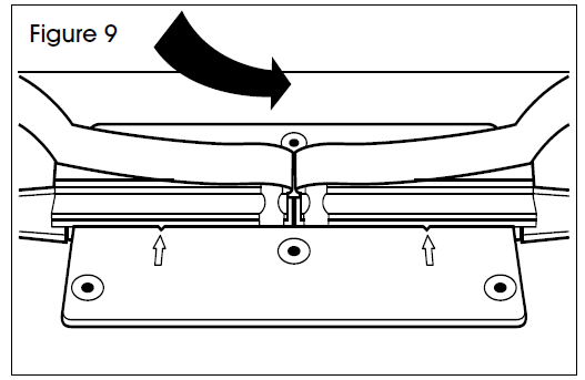
- Snap left-hand nozzle into place on white nozzle plate. An audible ‘click’ will be heard to confirm that the nozzle is engaged. (See Figure 9)
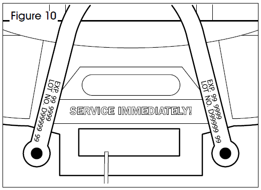
- Position the two black straps over top of the activation door with the expiration date and batch number visible. Do not twist or cross straps. Close activation door. (See Figure 10)
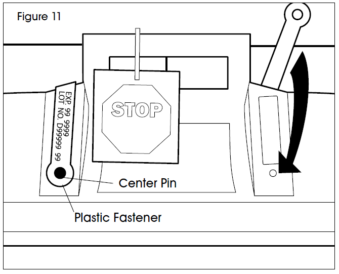
- Position nozzle activating straps over top of door and down raised area on either side of the door handle so the straps cover the labels on the activation door. (See Figure 11)
- Push plastic fastener into hole in door until flange is seated against the door. (See Figure 11)
- Push center pin of fastener until it snaps into place flush with fastener head. (See Figure 11)
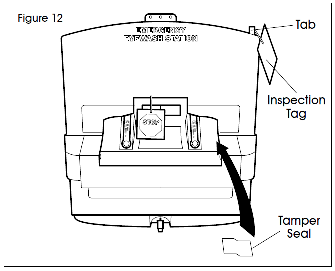
- Position tamper seal on middle right-hand side of door. Half the seal must be on the door and the other half on the unit surface. (See Figure 12)
- Attach lock or inspection tag through tab on cover. (See Figure 12)


![]()
[xyz-ips snippet=”download-snippet”]